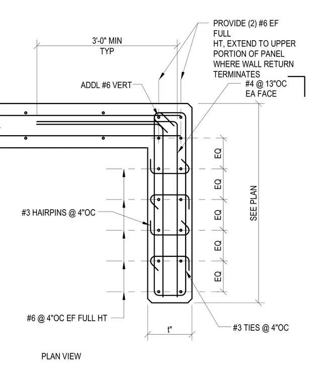
This concrete wall panel corner plan details the reinforcing bar layout and spacing at a return. Two number six vertical bars are provided at each face for the full height and extend to the upper portion of the panel where the wall return terminates, supplemented by additional number six vertical bars. Number four bars are spaced at thirteen inches on center at each face, and number six bars are spaced at four inches on center at each face for the full height. Number three ties and number three hairpins are spaced at four inches on center through the return.
t" 3'-0" MIN TYP EQ EQ EQ EQ EQ SEE PLAN PLAN VIEW #6 @ 4"OC EF FULL HT ADDL #6 VERT #3 TIES @ 4"OC #4 @ 13"OC EA FACE PROVIDE (2) #6 EF FULL HT, EXTEND TO UPPER PORTION OF PANEL WHERE WALL RETURN TERMINATES #3 HAIRPINS @ 4"OC
Members view this detail in full resolution, download the CAD files (SVG, PDF), and can adapt it in the built-in CAD editor — export DXF, DWG, or PDF.
Start membership