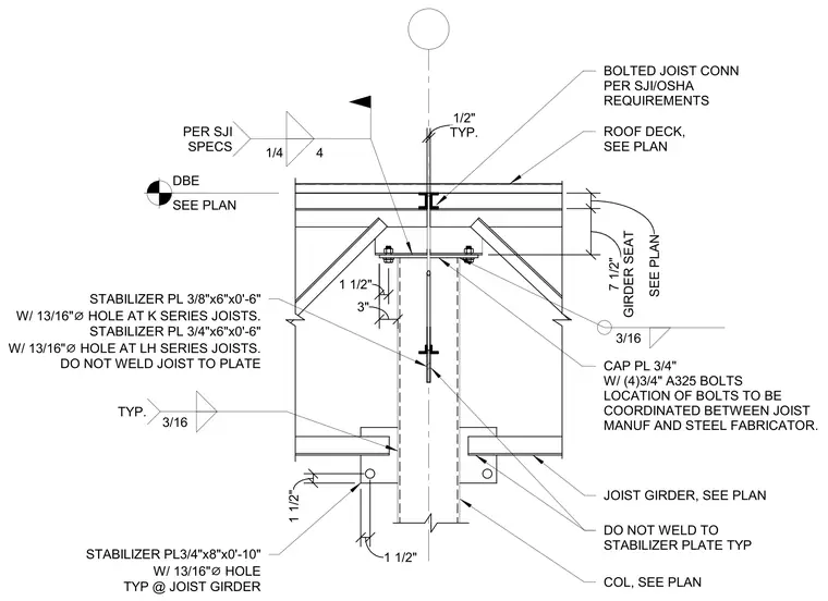
A steel joist girder is supported by a column with a three-quarter-inch thick cap plate. The girder is secured to the cap plate using four three-quarter-inch diameter A325 bolts, with the specific bolt locations coordinated between the joist manufacturer and the steel fabricator. Stabilizer plates are provided at the joist girder and at K-series or LH-series joists, featuring thirteen-sixteenths-inch diameter holes. The joist is left unwelded to the stabilizer plate, and the stabilizer plate is left unwelded to the girder. Bolted joist connections must comply with Steel Joist Institute and OSHA requirements, utilizing three-sixteenths-inch fillet welds at typical locations and one-quarter-inch fillet welds at four locations per Steel Joist Institute specifications.
STABILIZER PL 3/8"x6"x0'-6" W/ 13/16" ⌀ HOLE AT K SERIES JOISTS. STABILIZER PL 3/4"x6"x0'-6" W/ 13/16" ⌀ HOLE AT LH SERIES JOISTS. DO NOT WELD JOIST TO PLATE CAP PL 3/4" W/ (4)3/4" A325 BOLTS LOCATION OF BOLTS TO BE COORDINATED BETWEEN JOIST MANUF AND STEEL FABRICATOR. ROOF DECK, SEE PLAN BOLTED JOIST CONN PER SJI/OSHA REQUIREMENTS DBE SEE PLAN 1/4 4 PER SJI SPECS 3/16 TYP. 3/16 TYP. 1/2" GIRDER SEAT 7 1/2" SEE PLAN 1 1/2" 3"
Members view this detail in full resolution, download the CAD files (SVG, PDF), and can adapt it in the built-in CAD editor — export DXF, DWG, or PDF.
Start membership