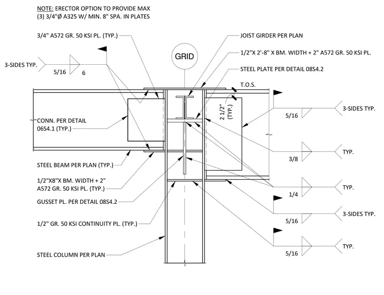
A heavy steel brace and beam connection frames into a steel column per plan. A joist girder sits at the top of the column with top of steel (T.O.S.) plates, accompanied by 1/2-inch Grade 50 continuity plates welded inside the column web. Gusset plates sized per detail 08S4.2 connect the steel beams and bracing using 5/16-inch and 1/4-inch fillet welds on three sides typically. A 3/4-inch A572 Grade 50 plate ties into the assembly with field welding and optional bolting utilizing up to three 3/4-inch diameter A325 bolts with a minimum 8-inch spacing. The erector is provided the option to utilize bolted plate connections per detail 06S4.1.
GRID STEEL COLUMN PER PLAN 3/8 TYP. 3/4" A572 GR. 50 KSI PL. (TYP.) GUSSET PL. PER DETAIL 08S4.2 T.O.S. STEEL PLATE PER DETAIL 08S4.2 JOIST GIRDER PER PLAN STEEL BEAM PER PLAN (TYP.) 1/4 TYP. 1/2"X8"X BM. WIDTH + 2" A572 GR. 50 KSI PL. (TYP.) 5/16 3-SIDES TYP. 5/16 3-SIDES TYP. 5/16 6 3-SIDES TYP. 1/2"X 2'-8" X BM. WIDTH + 2" A572 GR. 50 KSI PL. 1/2" GR. 50 KSI CONTINUITY PL. (TYP.) (TYP.) 2 1/2" 5/16 TYP. NOTE: ERECTOR OPTION TO PROVIDE MAX (3) 3/4"Ø A325 W/ MIN. 8" SPA. IN PLATES CONN. PER DETAIL 06S4.1 (TYP.)
Members view this detail in full resolution, download the CAD files (SVG, PDF), and can adapt it in the built-in CAD editor — export DXF, DWG, or PDF.
Start membership