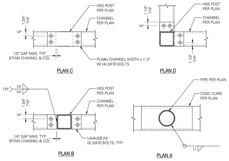
These structural plans show connection details between hollow structural section posts, channels, and pipes. The assemblies incorporate bolted connections using three-eighths-inch thick plates and four three-quarter-inch diameter bolts, or four-by-four by three-eighths-inch angles with two three-quarter-inch diameter bolts. Maximum gaps between the channels and columns are specified at one-quarter inch or one-half inch typically. Additional details show pipe installations relative to concrete curbs.
PLAN A PIPE PER PLAN CONC CURB PER PLAN [-] PLAN B L4x4x3/8 W/ (2) 3/4"Ø BOLTS, TYP CHANNEL PER PLAN HSS POST PER PLAN PLAN C PLAN D CHANNEL PER PLAN HSS POST PER PLAN C L TYP 1 3/4" 1/4 1/4 TYP CHANNEL PER PLAN HSS POST PER PLAN PL3/8x CHANNEL WIDTH x 1'-2" W/ (4) 3/4"Ø BOLTS BTWN CHANNEL & COL 1/2" GAP MAX, TYP C L TYP 1 3/4" C L TYP 1 1/2" TYP 1 1/2" BTWN CHANNEL & COL 1/4" GAP MAX, TYP
Members view this detail in full resolution, download the CAD files (SVG, PDF), and can adapt it in the built-in CAD editor — export DXF, DWG, or PDF.
Start membership