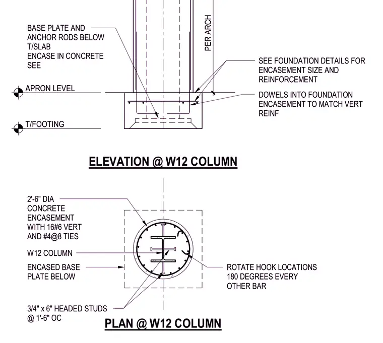
A W12 steel column is encased in a two-and-a-half-foot diameter circular concrete encasement extending from the top of the footing through the apron level and top of slab. The encasement is reinforced with sixteen number-six vertical bars and number-four ties spaced at eight inches on center, with hook locations rotated one hundred eighty degrees on every other bar. Three-quarter-inch by six-inch headed studs are welded to the steel column at one foot six inches on center. Dowels extend from the foundation encasement to match the vertical reinforcement, anchoring the column base plate and anchor rods located below the top of slab.
2'-6" DIA CONCRETE ENCASEMENT WITH 16#6 VERT AND #4@8 TIES ENCASED BASE PLATE BELOW W12 COLUMN PER ARCH ELEVATION @ W12 COLUMN PLAN @ W12 COLUMN APRON LEVEL BASE PLATE AND ANCHOR RODS BELOW T/SLAB ENCASE IN CONCRETE SEE T/FOOTING 3/4" x 6" HEADED STUDS @ 1'-6" OC DOWELS INTO FOUNDATION ENCASEMENT TO MATCH VERT REINF SEE FOUNDATION DETAILS FOR ENCASEMENT SIZE AND REINFORCEMENT ROTATE HOOK LOCATIONS 180 DEGREES EVERY OTHER BAR 2'-6" DIA CONCRETE ENCASEMENT WITH 16#6 VERT AND #4@8 TIES ENCASED BASE PLATE BELOW W12 COLUMN PER ARCH ELEVATION @ W12 COLUMN PLAN @ W12 COLUMN APRON LEVEL BASE PLATE AND ANCHOR RODS BELOW T/SLAB ENCASE IN CONCRETE SEE T/FOOTING 3/4" x 6" HEADED STUDS @ 1'-6" OC DOWELS INTO FOUNDATION ENCASEMENT TO MATCH VERT REINF SEE FOUNDATION DETAILS FOR ENCASEMENT SIZE AND REINFORCEMENT ROTATE HOOK LOCATIONS 180 DEGREES EVERY OTHER BAR
Members view this detail in full resolution, download the CAD files (SVG, PDF), and can adapt it in the built-in CAD editor — export DXF, DWG, or PDF.
Start membership