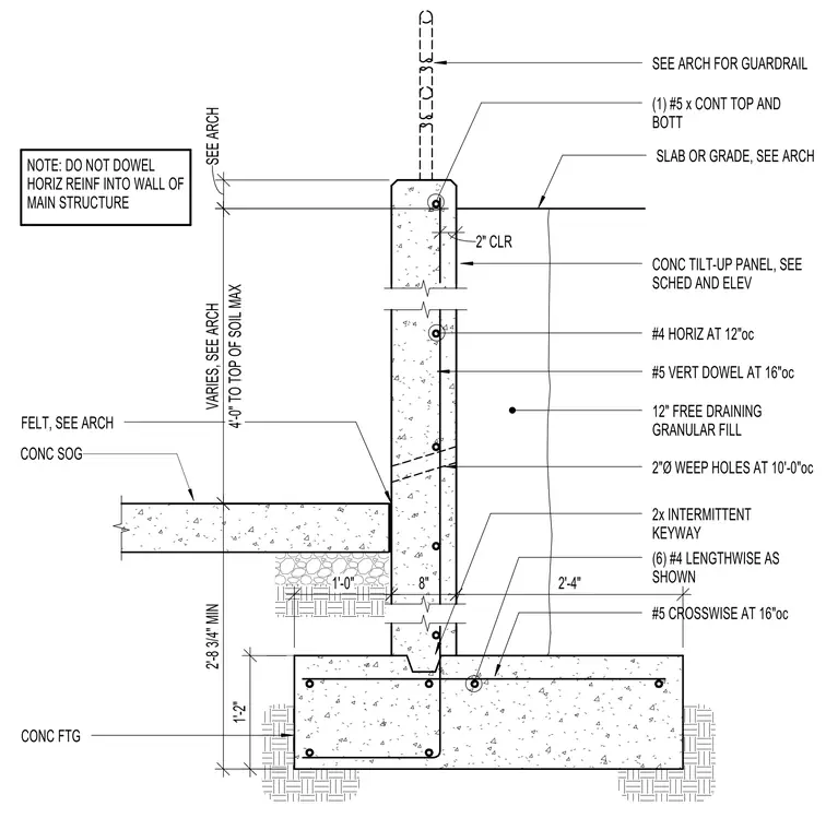
The assembly features a concrete tilt-up panel supported by a concrete footing with a two-inch intermittent keyway. The footing contains six number four lengthwise bars as shown and number five crosswise bars spaced at sixteen inches on center. The wall is reinforced with number five vertical dowels at sixteen inches on center and number four horizontal bars at twelve inches on center with a two-inch clearance. A twelve-inch layer of free-draining granular fill backs the wall, incorporating two-inch diameter weep holes spaced at ten feet on center. A concrete slab on grade interfaces with the wall above the footing with felt separation, leaving horizontal reinforcement un-doweled into the main structure wall. Guardrail attachments and soil heights vary per architectural drawings up to a maximum of four feet.
(6) #4 LENGTHWISE AS SHOWN 2'-8 3/4" MIN #5 CROSSWISE AT 16"oc 2x INTERMITTENT KEYWAY 2"Ø WEEP HOLES AT 10'-0"oc 12" FREE DRAINING GRANULAR FILL #4 HORIZ AT 12"oc #5 VERT DOWEL AT 16"oc CONC TILT-UP PANEL, SEE SCHED AND ELEV SEE ARCH FOR GUARDRAIL (1) #5 x CONT TOP AND BOTT SLAB OR GRADE, SEE ARCH FELT, SEE ARCH NOTE: DO NOT DOWEL HORIZ REINF INTO WALL OF MAIN STRUCTURE SEE ARCH 4'-0" TO TOP OF SOIL MAX VARIES, SEE ARCH 2" CLR 2'-4" 8" 1'-0" 1'-2" CONC FTG CONC SOG
Members view this detail in full resolution, download the CAD files (SVG, PDF), and can adapt it in the built-in CAD editor — export DXF, DWG, or PDF.
Start membership