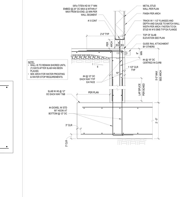
Structural connection at an elevator pit where a concrete slab meets a metal stud wall. The assembly features a reinforced concrete foundation slab with number four dowels featuring standard ninety-degree hooks at twelve inches on center at the bottom. The concrete pit walls include number four reinforcing bars at twelve inches on center each way on each face, with a continuous number five bar and number four bars at eighteen inches on center centered in the curb. The cold-formed steel metal stud wall bears on a track with one and one-half inch flanges fastened to each stud with number ten self-tapping metal screws at each flange, anchored using five-eighths-inch diameter Titen HD anchors with seven-inch minimum embedment at twenty-four inches on center maximum and within four inches from each end, with a minimum of two per wall segment. General notes specify that the wall is to remain shored until seven days after the slab has been placed, and coordination with architectural drawings is required for waterproofing and waterstop requirements.
MIN 6" TYP 1 1/2" CLR PER SCHED LAP SPLICE 2' - 0" SEE ARCH 5'-0" MAX 2'-0" TYP #4 DOWEL W/ STD 90° HOOK AT BOTTOM @ 12" OC #4 @ 12" OC EACH WAY TYP EA FACE TOP OF SLAB ELEVATION SEE PLAN SLAB W/ #5 @ 12" OC EACH WAY T&B 1 6 NOTE: • WALL IS TO REMAIN SHORED UNTIL (7) DAYS AFTER SLAB HAS BEEN PLACED. • SEE ARCH FOR WATER PROOFING & WATER STOP REQUIREMENTS. 10" 3" CLR PER PLAN 3" CLR GUIDE RAIL ATTACHMENT BY OTHERS EQ EQ METAL STUD WALL PER PLAN FINISH PER ARCH ARCH PER TRACK W/ 1 1/2" FLANGES AND DEPTH AND GAUGE TO MATCH WALL WIDTH PER ARCH. FASTEN TO EA STUD W/ #10 SMS TYP EA FLANGE 5/8"ø TITEN HD W/ 7" MIN EMBED @ 24" OC MAX & WITHIN 4" MAX FROM EA END, (2) MIN PER WALL SEGMENT # 5 CONT #4 @ 18" OC CENTRED IN CURB
Members view this detail in full resolution, download the CAD files (SVG, PDF), and can adapt it in the built-in CAD editor — export DXF, DWG, or PDF.
Start membership