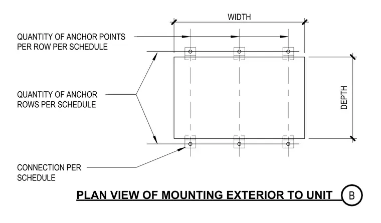
An exterior unit mounting assembly is detailed in plan view with dimensional indicators for width and depth. Anchor points are arranged in rows and columns with quantities determined per schedule. Individual connection plates and fastening locations are marked along the perimeter of the unit.
QUANTITY OF ANCHOR POINTS PER ROW PER SCHEDULE QUANTITY OF ANCHOR ROWS PER SCHEDULE PLAN VIEW OF MOUNTING EXTERIOR TO UNIT DEPTH WIDTH CONNECTION PER SCHEDULE B
Members view this detail in full resolution, download the CAD files (SVG, PDF), and can adapt it in the built-in CAD editor — export DXF, DWG, or PDF.
Start membership