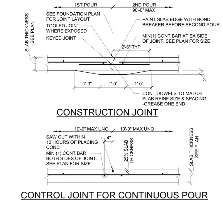
The construction joint detail features a keyed slab edge between a first and second concrete pour, separated by a painted bond breaker and reinforced with continuous dowels where one end is greased. A minimum of one continuous reinforcing bar is placed on each side of the joint, sized per plan. The control joint detail shows a saw-cut groove extending twenty-five percent of the slab thickness, accompanied by continuous reinforcing bars running parallel to the joint on both sides. A tooled joint is applied where the concrete is exposed, and maximum pour spacing limits are defined.
1ST POUR 2ND POUR 90'-0" MAX SEE FOUNDATION PLAN FOR JOINT LAYOUT TOOLED JOINT WHERE EXPOSED PAINT SLAB EDGE WITH BOND BREAKER BEFORE SECOND POUR MIN(1) CONT BAR AT EA SIDE OF JOINT. SEE PLAN FOR SIZE SEE PLAN SLAB THICKNESS 2" KEYED JOINT 1'-0" 1'-0" 1'-0" CONSTRUCTION JOINT 10'-0" MAX UNO 10'-0" MAX UNO 4" SAW CUT WITHIN 12 HOURS OF PLACING CONC MIN (1) CONT BAR BOTH SIDES OF JOINT. SEE PLAN FOR SIZE THICKNESS 25% SLAB SEE PLAN SLAB THICKNESS CONTROL JOINT FOR CONTINUOUS POUR 2'-6" TYP CONT DOWELS TO MATCH SLAB REINF SIZE & SPACING -GREASE ONE END
Members view this detail in full resolution, download the CAD files (SVG, PDF), and can adapt it in the built-in CAD editor — export DXF, DWG, or PDF.
Start membership