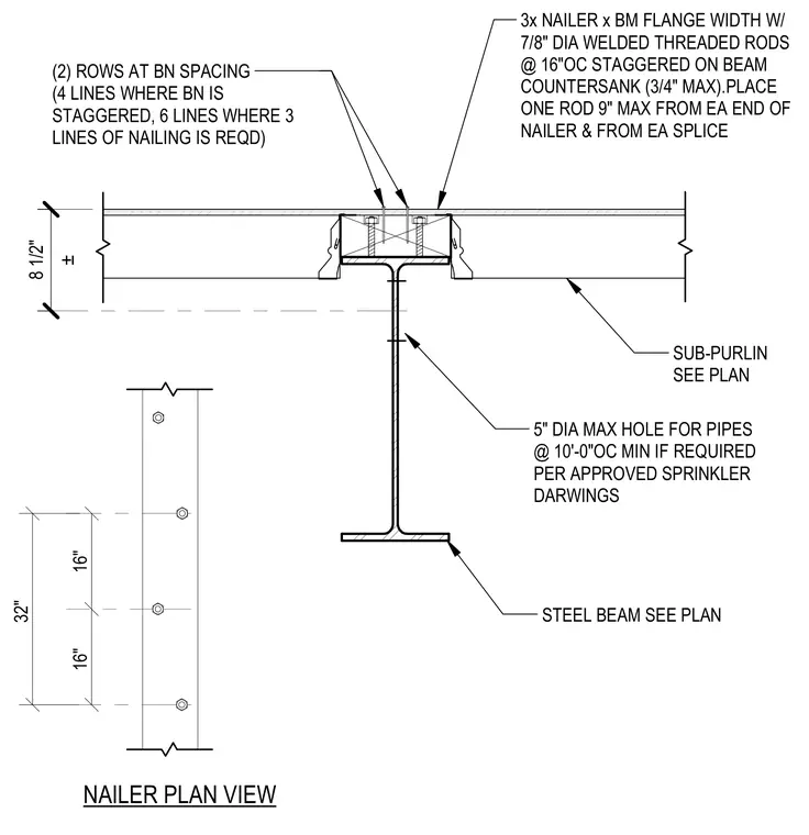
A wood nailer matching the beam flange width is anchored to the top flange using seven-eighths-inch diameter welded threaded rods spaced at sixteen inches on center staggered. Countersunk nuts are set to a maximum three-quarter-inch depth. The nailer is placed with one rod positioned a maximum of nine inches from each end of the nailer and from each splice. Sub-purlins connect adjacent to the nailer assembly. The steel beam web accommodates pipe penetrations up to five inches in diameter spaced at ten feet on center minimum as required per approved sprinkler drawings.
± 8 1/2" 32" 16" 16" NAILER PLAN VIEW STEEL BEAM SEE PLAN 5" DIA MAX HOLE FOR PIPES @ 10'-0"OC MIN IF REQUIRED PER APPROVED SPRINKLER DARWINGS SUB-PURLIN SEE PLAN (2) ROWS AT BN SPACING (4 LINES WHERE BN IS STAGGERED, 6 LINES WHERE 3 LINES OF NAILING IS REQD) 3x NAILER x BM FLANGE WIDTH W/ 7/8" DIA WELDED THREADED RODS @ 16"OC STAGGERED ON BEAM COUNTERSANK (3/4" MAX).PLACE ONE ROD 9" MAX FROM EA END OF NAILER & FROM EA SPLICE
Members view this detail in full resolution, download the CAD files (SVG, PDF), and can adapt it in the built-in CAD editor — export DXF, DWG, or PDF.
Start membership