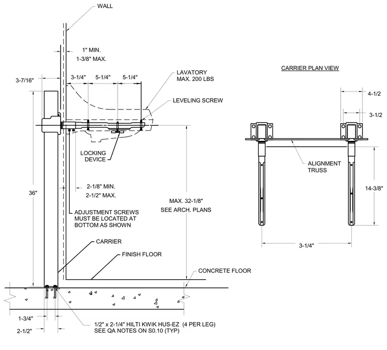
The lavatory carrier system is anchored to the concrete floor using four 1/2-inch by 2-1/4-inch Hilti Kwik Hus-Ez concrete screws per leg. Adjustment screws must be positioned at the bottom as shown, providing a minimum of 2-1/8 inches and a maximum of 2-1/2 inches of clearance. The lavatory fixture accommodates a maximum weight of 200 pounds and utilizes a leveling screw and locking device for secure positioning. A carrier plan view details the alignment truss spanning between vertical supports.
LEVELING SCREW MAX. 32-1/8" SEE ARCH. PLANS LOCKING DEVICE 3-1/4" 14-3/8" 3-1/4" ALIGNMENT TRUSS 2-1/8" MIN. 2-1/2" MAX. ADJUSTMENT SCREWS MUST BE LOCATED AT BOTTOM AS SHOWN 1" MIN. 1-3/8" MAX. 3-7/16" 36" 2-1/2" 1-3/4" 4-1/2 3-1/2 1/2" x 2-1/4" HILTI KWIK HUS-EZ (4 PER LEG) 5-1/4" 5-1/4" LAVATORY FINISH FLOOR CONCRETE FLOOR MAX. 200 LBS WALL CARRIER PLAN VIEW CARRIER SEE QA NOTES ON S0.10 (TYP)
Members view this detail in full resolution, download the CAD files (SVG, PDF), and can adapt it in the built-in CAD editor — export DXF, DWG, or PDF.
Start membership