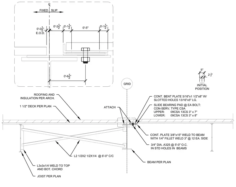
This structural roof expansion joint detail connects a framing beam per plan to a supporting grid line with a sliding bearing assembly. A continuous 3/8-inch by 15-inch plate is welded to the beam using three-inch quarter-inch fillet welds at each side. A continuous bent plate measuring 5/16-inch by 1-1/2-inch by 8-inch features 13/16-inch by 5-inch slotted holes to accommodate movement. A Con-Serv slide bearing assembly, Type CSA, is placed at each bolt location with upper dimensions of 09CSA 13CS 3 inches by 7 inches and lower dimensions of 09CSA 13CS 3 inches by 8 inches. The assembly is secured using 3/4-inch diameter ASTM A325 bolts at 5 feet on center in standard holes in the beams. A joist per plan with angles measuring L2-1/2 by 2-1/2 by 1/4 at 6 feet on center and L3 by 3 by 1/4 welded to the top and bottom chord supports the 1-1/2-inch deck per plan. Roofing and insulation are provided per the architectural drawings.
GRID BEAM PER PLAN JOIST PER PLAN 1 1/2" DECK PER PLAN ROOFING AND INSULATION PER ARCH. 3/4" DIA. A325 @ 5'-0" O.C. IN STD HOLES IN BEAMS L3x3x1/4 WELD TO TOP AND BOT. CHORD ATTACH CONT. BENT PLATE 5/16"x1 1/2"x8" W/ SLOTTED HOLES 13/16"x5" LG. SLIDE BEARING PAD @ EA BOLT: CON-SERV, TYPE CSA UPPER: 09CSA 13CS 3" x 7" LOWER: 09CSA 13CS 3" x 8" 5" 2 1 2 " INITIAL POSITION CONT. PLATE 3/8"x15" WELD TO BEAM WITH 1/4" FILLET WELD 3" @ 12 EA. SIDE L2 1/2X2 1/2X1/4 @ 6'-0" C/C SLIP FIXED CL 0'-61 2" 0'-11 2" 0'-5" 0'-11 2" 0'-21 2" 0'-01 2" E.O.D.
Members view this detail in full resolution, download the CAD files (SVG, PDF), and can adapt it in the built-in CAD editor — export DXF, DWG, or PDF.
Start membership