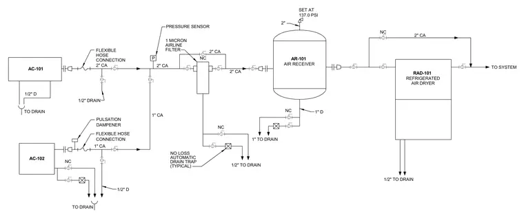
Compressed air schematic diagram detailing components AC-101 and AC-102 feeding into a shared 2-inch compressed air line via flexible hose connections and pulsation dampeners. The system includes a 1-micron airline filter, a pressure sensor, and an air receiver tank designated as AR-101 with a safety relief valve set at 137.0 PSI. Air is then routed through a refrigerated air dryer RAD-101 before feeding into the building system. Drainage lines ranging from 1/2-inch to 1-inch are provided at the compressors, filter, receiver, and dryer with typical no-loss automatic drain traps.
TO DRAIN 1/2" D 1" TO DRAIN NC 1" D 2" CA 2" CA AIR RECEIVER AR-101 2" 137.0 PSI SET AT NC 1/2" TO DRAIN AIRLINE FILTER 1 MICRON NC 2" CA 2" CA NC 2" CA AC-101 RAD-101 TO DRAIN 1" CA FLEXIBLE HOSE CONNECTION 1" CA P PRESSURE SENSOR FLEXIBLE HOSE CONNECTION 1/2" DRAIN REFRIGERATED AIR DRYER NO LOSS AUTOMATIC DRAIN TRAP AC-102 NC 1/2" D PULSATION DAMPENER (TYPICAL) 1/2" TO DRAIN TO SYSTEM
Members view this detail in full resolution, download the CAD files (SVG, PDF), and can adapt it in the built-in CAD editor — export DXF, DWG, or PDF.
Start membership