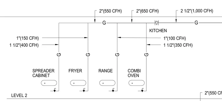
This diagram details the gas piping layout for commercial kitchen equipment on Level 2 with specified pipe diameters and cubic feet per hour flow rates. The main gas line steps up from two inches at five hundred fifty CFH to two and one-half inches at one thousand CFH. Drop lines serve a spreader cabinet, a fryer, a range, and a combi oven with individual branch sizes ranging from one inch to two and one-half inches.
1 1/2"(350 CFH) 1 1/2"(400 CFH) 1"(150 CFH) 1"(100 CFH) 2"(550 CFH) 2"(550 CFH) LEVEL 2 2"(650 CFH) 2 1/2"(1,000 CFH) KITCHEN - - - G G G G - G SPREADER CABINET FRYER RANGE COMBI OVEN G
Members view this detail in full resolution, download the CAD files (SVG, PDF), and can adapt it in the built-in CAD editor — export DXF, DWG, or PDF.
Start membership