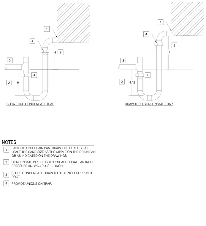
Blow-through and draw-through condensate trap configurations connect to a fan coil unit drain pan with drain lines sized at least equal to the nipple or as indicated on the drawings. Condensate pipe height "H" equals fan inlet pressure in inches of water column plus one inch for blow-through units, and half that height for draw-through units. The condensate drain slopes toward the receptor at one-eighth inch per foot. Unions are provided on the trap for maintenance access.
H H BLOW THRU CONDENSATE TRAP H / 2 H DRAW THRU CONDENSATE TRAP 1 4 3 2 2 4 1 4 3 2 2 4 NOTES FAN COIL UNIT DRAIN PAN. DRAIN LINE SHALL BE AT LEAST THE SAME SIZE AS THE NIPPLE ON THE DRAIN PAN OR AS INDICATED ON THE DRAWINGS. CONDENSATE PIPE HEIGHT "H" SHALL EQUAL FAN INLET PRESSURE (IN. WC.) PLUS 1.0 INCH. SLOPE CONDENSATE DRAIN TO RECEPTOR AT 1/8" PER FOOT. PROVIDE UNIONS ON TRAP. 1 2 3 4
Members view this detail in full resolution, download the CAD files (SVG, PDF), and can adapt it in the built-in CAD editor — export DXF, DWG, or PDF.
Start membership