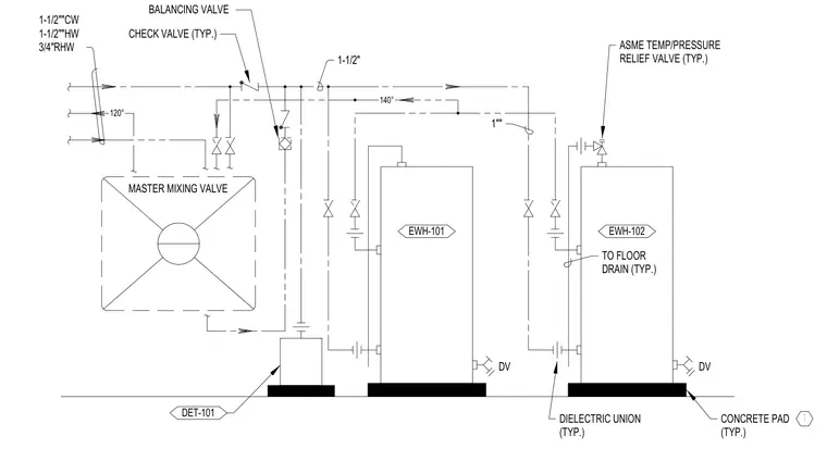
An electric water heater installation diagram showing two water heaters mounted on concrete pads with cold water supply, hot water supply, and recirculated hot water return piping. The system incorporates a master mixing valve, balancing valves, check valves, and dielectric unions at pipe transitions. An ASME temperature and pressure relief valve is installed on each heater with discharge piping routed to a floor drain. Drain valves are provided at the base of the water heaters.
120° 140° DV DV EWH-102 EWH-101 DET-101 CHECK VALVE (TYP.) BALANCING VALVE ASME TEMP/PRESSURE RELIEF VALVE (TYP.) TO FLOOR DRAIN (TYP.) DIELECTRIC UNION (TYP.) CONCRETE PAD (TYP.) 1 1-1/2""CW 1-1/2""HW 3/4"RHW 1"" 1-1/2" MASTER MIXING VALVE
Members view this detail in full resolution, download the CAD files (SVG, PDF), and can adapt it in the built-in CAD editor — export DXF, DWG, or PDF.
Start membership