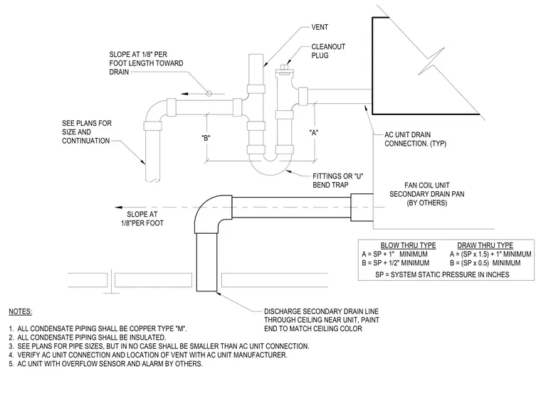
Condensate piping connects to the air conditioning unit drain connection with a typical U-bend trap and a cleanout plug located above the trap. Pipe dimensions 'A' and 'B' are determined by whether the system is a blow-through or draw-through type, using the system static pressure. All condensate piping is specified as Type M copper and requires insulation. A secondary drain line routes from the secondary drain pan through the ceiling near the unit, with the end painted to match the ceiling color. Piping is pitched at one-eighth inch per foot toward the drain.
NOTES: 1. ALL CONDENSATE PIPING SHALL BE COPPER TYPE "M". 2. ALL CONDENSATE PIPING SHALL BE INSULATED. 3. SEE PLANS FOR PIPE SIZES, BUT IN NO CASE SHALL BE SMALLER THAN AC UNIT CONNECTION. 4. VERIFY AC UNIT CONNECTION AND LOCATION OF VENT WITH AC UNIT MANUFACTURER. 5. AC UNIT WITH OVERFLOW SENSOR AND ALARM BY OTHERS. "B" "A" AC UNIT DRAIN CONNECTION. (TYP) FITTINGS OR "U" BEND TRAP CLEANOUT PLUG SLOPE AT 1/8" PER FOOT LENGTH TOWARD DRAIN SEE PLANS FOR SIZE AND CONTINUATION FAN COIL UNIT SECONDARY DRAIN PAN (BY OTHERS) SLOPE AT 1/8"PER FOOT DISCHARGE SECONDARY DRAIN LINE THROUGH CEILING NEAR UNIT, PAINT END TO MATCH CEILING COLOR VENT BLOW THRU TYPE A = SP + 1" MINIMUM B = SP + 1/2" MINIMUM A = (SP x 1.5) + 1" MINIMUM B = (SP x 0.5) MINIMUM DRAW THRU TYPE SP = SYSTEM STATIC PRESSURE IN INCHES
Members view this detail in full resolution, download the CAD files (SVG, PDF), and can adapt it in the built-in CAD editor — export DXF, DWG, or PDF.
Start membership