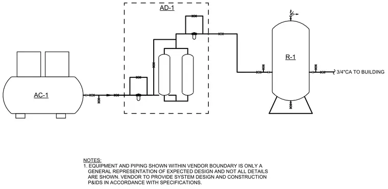
This diagram outlines the piping and equipment arrangement for a compressed air system originating from compressor AC-1. The discharge line feeds into an AD-1 vendor-supplied treatment assembly, which is noted as a general representation requiring vendor-provided P&IDs per specifications. From the treatment boundary, the compressed air flows through isolation valves into receiver tank R-1. A three-quarter-inch compressed air line exits the receiver tank to supply the building.
AD-1 1. NOTES: EQUIPMENT AND PIPING SHOWN WITHIN VENDOR BOUNDARY IS ONLY A GENERAL REPRESENTATION OF EXPECTED DESIGN AND NOT ALL DETAILS ARE SHOWN. VENDOR TO PROVIDE SYSTEM DESIGN AND CONSTRUCTION P&IDS IN ACCORDANCE WITH SPECIFICATIONS. 3/4"CA TO BUILDING AC-1 R-1
Members view this detail in full resolution, download the CAD files (SVG, PDF), and can adapt it in the built-in CAD editor — export DXF, DWG, or PDF.
Start membership