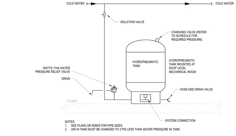
A cold water hydropneumatic tank is mounted at the roof level mechanical room floor with a system connection to the cold water supply piping. An isolation valve is installed on the cold water line above the tank, and a hose end drain valve is connected near the tank base. A Watts 174A water pressure relief valve ties into the system with a drain line. A charging valve is located at the top of the tank for pressurization per schedule.
FLOOR NOTES: 1. SEE PLANS OR RISER FOR PIPE SIZES. 2. AIR IN TANK MUST BE CHARGED TO 2 PSI LESS THAN WATER PRESSURE IN TANK. COLD WATER HYDROPNEUMATIC TANK HYDROPNEUMATIC TANK MOUNTED AT ROOF LEVEL MECHANICAL ROOM ISOLATION VALVE HOSE END DRAIN VALVE COLD WATER SYSTEM CONNECTION CHARGING VALVE (REFER TO SCHEDULE FOR REQUIRED PRESSURE) DRAIN WATTS 174A WATER PRESSURE RELIEF VALVE
Members view this detail in full resolution, download the CAD files (SVG, PDF), and can adapt it in the built-in CAD editor — export DXF, DWG, or PDF.
Start membership