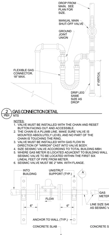
The gas drop from the main connects through a manual main shut-off valve to a ground joint union and an eighteen-inch maximum flexible gas connector. A vertical drip leg of the same size as the drop extends six inches below the connection with a capped end. The seismic gas valve is supported on Unistrut framing anchored to the concrete wall or slab and must be installed level with the flow direction aligned with the cast arrow. The valve requires a two-inch minimum flanged connection located within the first six lineal feet of pipe from the gas meter.
FLEXIBLE GAS CONNECTOR. 18" MAX. DRIP LEG SAME SIZE AS DROP 6" VERTICAL GROUND JOINT UNION MANUAL MAIN SHUT-OFF VALVE DROP FROM MAIN. SEE PLAN FOR SIZE. FLOW A 6" NOTES: 1. VALVE MUST BE INSTALLED WITH THE CHAIN AND RESET BUTTON FACING OUT AND ACCESSIBLE. 2. THE CHAIN IS A PLUMB LINE. MAKE SURE VALVE IS MOUNTED ABSOLUTELY LEVEL AND NO PART OF THE CHAIN IS TOUCHING THE RING. 3. VALVE MUST BE INSTALLED WITH GAS FLOW IN DIRECTION OF "ARROW" CAST INTO VALVE BODY. 4. SIZE SEISMIC VALVE ACCORDING TO TOTAL BUILDING MBH. 5. WHERE GAS METER IS LOCATED ADJACENT TO BUILDING WALL LINEAL FEET OF PIPE FROM METER. 6. SEISMIC VALVE MUST BE 2" MIN. WITH FLANGE. INTO BUILDING UNISTRUT SUPPORT (TYP.) ANCHOR TO WALL (TYP.) CONCRETE SLAB LINE SIZE SAME AS SEISMIC VALVE GAS METER CONCRETE SLAB 6" SEISMIC VALVE TO BE LOCATED WITHIN THE FIRST SIX NTS P501 2 GAS CONNECTION DETAIL
Members view this detail in full resolution, download the CAD files (SVG, PDF), and can adapt it in the built-in CAD editor — export DXF, DWG, or PDF.
Start membership