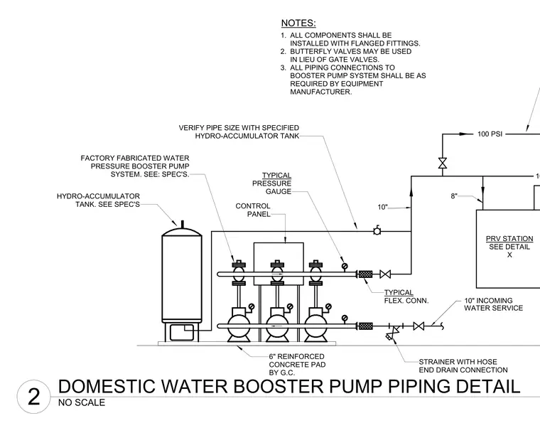
A factory fabricated water pressure booster pump system rests on a six-inch reinforced concrete pad provided by the general contractor. A hydro-accumulator tank connects alongside the multi-pump skid which features a control panel, typical pressure gauges, and typical flexible connections. Incoming ten-inch water service incorporates a ten-inch incoming strainer with hose end drain connection and flanged fittings. An eight-inch pressure reducing valve station connects downstream with pipe sizes verified against the specified hydro-accumulator tank.
8" PRV STATION SEE DETAIL X 1. ALL COMPONENTS SHALL BE INSTALLED WITH FLANGED FITTINGS. 2. BUTTERFLY VALVES MAY BE USED IN LIEU OF GATE VALVES. 3. ALL PIPING CONNECTIONS TO BOOSTER PUMP SYSTEM SHALL BE AS REQUIRED BY EQUIPMENT MANUFACTURER. FACTORY FABRICATED WATER PRESSURE BOOSTER PUMP SYSTEM. SEE: SPEC'S. HYDRO-ACCUMULATOR TANK. SEE SPEC'S CONTROL PANEL 10" INCOMING STRAINER WITH HOSE END DRAIN CONNECTION WATER SERVICE 100 PSI 100 PSI 10" TYPICAL FLEX. CONN. 6" REINFORCED CONCRETE PAD BY G.C. TYPICAL PRESSURE GAUGE VERIFY PIPE SIZE WITH SPECIFIED HYDRO-ACCUMULATOR TANK NOTES: NO SCALE 2 DOMESTIC WATER BOOSTER PUMP PIPING DETAIL
Members view this detail in full resolution, download the CAD files (SVG, PDF), and can adapt it in the built-in CAD editor — export DXF, DWG, or PDF.
Start membership