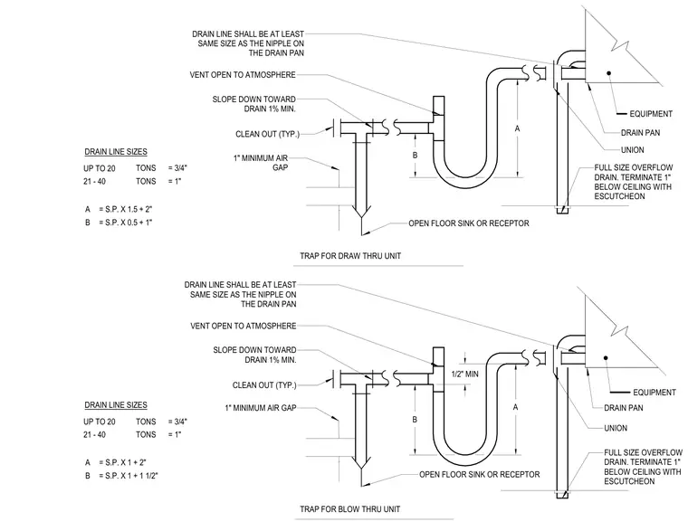
Typical HVAC condensate drain trap configurations for both draw-thru and blow-thru units include sizing formulas and dimensional requirements. The drain line connects to the equipment drain pan via a union and maintains a slope down toward the drain of one percent minimum. A vent open to the atmosphere is included alongside a typical cleanout, discharging into an open floor sink or receptor with a one-inch minimum air gap. A full-size overflow drain terminates one inch below the ceiling with an escutcheon. Sizing tables and formulas define trap dimensions based on equipment tonnage and static pressure.
VENT OPEN TO ATMOSPHERE CLEAN OUT (TYP.) DRAIN LINE SHALL BE AT LEAST SAME SIZE AS THE NIPPLE ON THE DRAIN PAN = S.P. X 0.5 + 1" = S.P. X 1.5 + 2" B A = 1" = 3/4" 21 - 40 UP TO 20 TONS TONS DRAIN PAN SLOPE DOWN TOWARD DRAIN 1% MIN. OPEN FLOOR SINK OR RECEPTOR UNION TRAP FOR DRAW THRU UNIT EQUIPMENT VENT OPEN TO ATMOSPHERE CLEAN OUT (TYP.) DRAIN LINE SHALL BE AT LEAST SAME SIZE AS THE NIPPLE ON THE DRAIN PAN = S.P. X 1 + 1 1/2" = S.P. X 1 + 2" B A = 1" = 3/4" 21 - 40 UP TO 20 TONS TONS DRAIN PAN SLOPE DOWN TOWARD DRAIN 1% MIN. OPEN FLOOR SINK OR RECEPTOR UNION TRAP FOR BLOW THRU UNIT EQUIPMENT 1" MINIMUM AIR GAP 1" MINIMUM AIR GAP FULL SIZE OVERFLOW DRAIN. TERMINATE 1" BELOW CEILING WITH ESCUTCHEON FULL SIZE OVERFLOW DRAIN. TERMINATE 1" BELOW CEILING WITH ESCUTCHEON A B A B 1/2" MIN DRAIN LINE SIZES DRAIN LINE SIZES
Members view this detail in full resolution, download the CAD files (SVG, PDF), and can adapt it in the built-in CAD editor — export DXF, DWG, or PDF.
Start membership