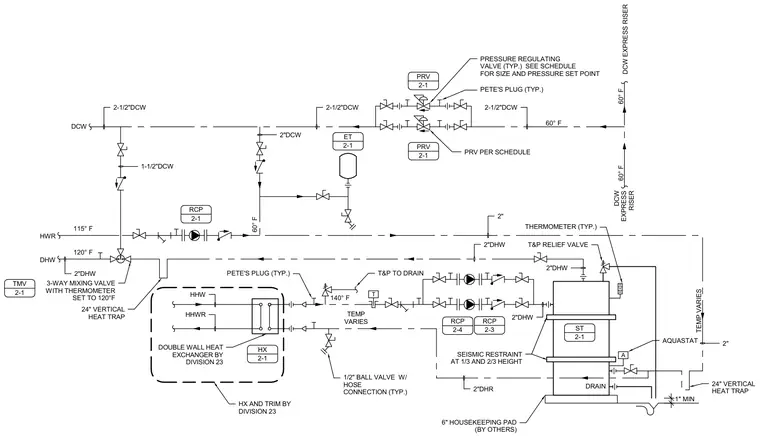
This plumbing diagram details the piping schematic for a double-wall heat exchanger and storage tank assembly. The system integrates domestic cold water lines fed through pressure-reducing valves, expansion tanks, and recirculating pumps, connecting to a heat exchanger provided by Division 23. A three-way mixing valve with a thermometer is set to 120 degrees Fahrenheit to temper domestic hot water supply. The storage tank rests on a six-inch concrete housekeeping pad and includes vertical heat traps, a temperature and pressure relief valve routed to a drain, and seismic restraints at one-third and two-thirds height.
T A 1" MIN AQUASTAT HX AND TRIM BY DIVISION 23 PETE'S PLUG (TYP.) PRV PER SCHEDULE PETE'S PLUG (TYP.) PRESSURE REGULATING VALVE (TYP.) SEE SCHEDULE FOR SIZE AND PRESSURE SET POINT 2-1/2"DCW 2-1/2"DCW 2"DHW HHW HHWR 1/2" BALL VALVE W/ HOSE CONNECTION (TYP.) 2"DCW 3-WAY MIXING VALVE WITH THERMOMETER SET TO 120°F 2-1/2"DCW T&P TO DRAIN DOUBLE WALL HEAT EXCHANGER BY DIVISION 23 6" HOUSEKEEPING PAD (BY OTHERS) 2" 2"DHR 2"DHW 2"DHW 2"DHW T&P RELIEF VALVE THERMOMETER (TYP.) 24" VERTICAL HEAT TRAP 24" VERTICAL HEAT TRAP 2" 1-1/2"DCW SEISMIC RESTRAINT AT 1/3 AND 2/3 HEIGHT ET 2-1 PRV 2-1 PRV 2-1 RCP 2-1 HX 2-1 60° F 140° F 60° F 60° F TEMP VARIES DCW DHW HWR DCW EXPRESS RISER DCW EXPRESS RISER 115° F TMV 2-1 ST 2-1 DRAIN 120° F RCP 2-3 60° F TEMP VARIES RCP 2-4
Members view this detail in full resolution, download the CAD files (SVG, PDF), and can adapt it in the built-in CAD editor — export DXF, DWG, or PDF.
Start membership