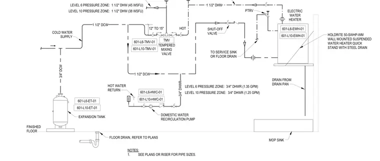
This diagram details the piping and equipment arrangement for an electric domestic water heater installation. The setup includes a wall-mounted suspended water heater supported by a quick stand with a steel drain pan discharging to a mop sink or floor drain. A cold water supply line branches to an expansion tank and feeds the water heater through appropriate shut-off valves and a pressure-temperature relief valve. A tempered mixing valve regulates outgoing domestic hot water temperatures, while a domestic water recirculation pump handles the hot water return loop. Pipe sizing and specific zone parameters are indicated for level-specific configurations.
12" TO 15" HOT NOTES: 1. SEE PLANS OR RISER FOR PIPE SIZES. TO SERVICE SINK OR FLOOR DRAIN SHUT-OFF VALVE PTRV COLD WATER SUPPLY EXPANSION TANK HOT WATER RETURN FLOOR DRAIN, REFER TO PLANS MOP SINK TEMPERED MIXING VALVE DOMESTIC WATER RECIRCULATION PUMP FINISHED FLOOR TMV ELECTRIC WATER HEATER DRAIN FROM DRAIN PAN 601-L6-EWH-01 HOLDRITE 50-SWHP-WM WALL MOUNTED SUSPENDED WATER HEATER QUICK STAND WITH STEEL DRAIN LEVEL 6 PRESSURE ZONE: 1 1/2" DHW (45 WSFU) 3/4" DCW 1 1/2" DCW 1 1/2" DHW 1 1/2" DCW LEVEL 10 PRESSURE ZONE: 1 1/2" DHW (38 WSFU) LEVEL 6 PRESSURE ZONE: 3/4" DHWR (1.35 GPM) LEVEL 10 PRESSURE ZONE: 3/4" DHWR (1.25 GPM) 3/4" DHWR 601-L10-EWH-01 601-L6-TMV-01 601-L10-TMV-01 601-L6-ET-01 601-L10-ET-01 601-L6-HWC-01 601-L10-HWC-01
Members view this detail in full resolution, download the CAD files (SVG, PDF), and can adapt it in the built-in CAD editor — export DXF, DWG, or PDF.
Start membership