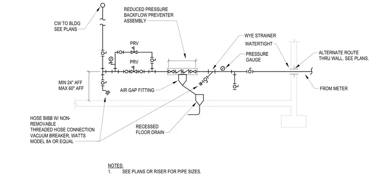
Incoming cold water from the meter routes through a watertight wall penetration into the building interior. The service line includes a pressure gauge, a watertight wye strainer, and a reduced pressure backflow preventer assembly positioned between twenty-four and sixty inches above the finished floor. An air gap fitting links the backflow preventer discharge to a recessed floor drain. Downstream of the backflow prevention, parallel pressure reducing valves manage distribution to the domestic water system, complemented by a hose bibb with a non-removable threaded hose connection vacuum breaker.
NOTES: 1. SEE PLANS OR RISER FOR PIPE SIZES. PRV PRV CW TO BLDG SEE PLANS HOSE BIBB W/ NON- REMOVABLE THREADED HOSE CONNECTION VACUUM BREAKER, WATTS MODEL 8A OR EQUAL RECESSED FLOOR DRAIN FROM METER ALTERNATE ROUTE THRU WALL. SEE PLANS. PRESSURE GAUGE WATERTIGHT WYE STRAINER AIR GAP FITTING REDUCED PRESSURE BACKFLOW PREVENTER ASSEMBLY MIN 24" AFF MAX 60" AFF
Members view this detail in full resolution, download the CAD files (SVG, PDF), and can adapt it in the built-in CAD editor — export DXF, DWG, or PDF.
Start membership