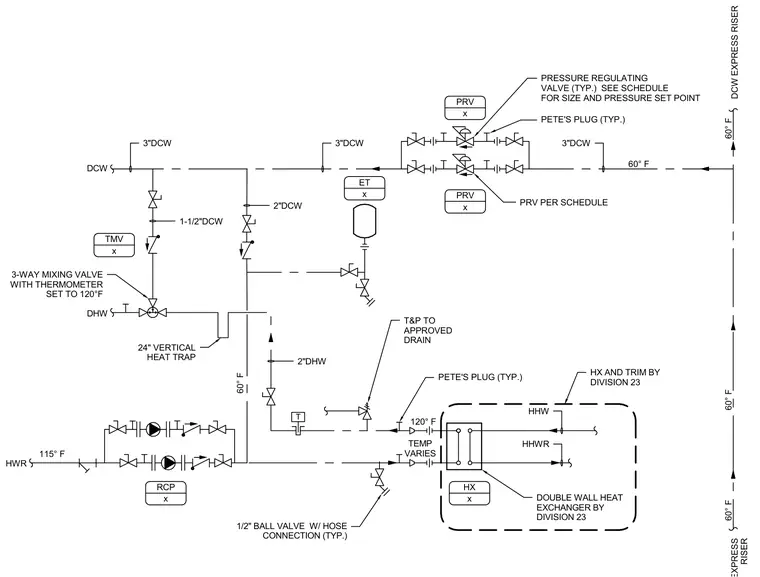
This plumbing diagram details a double wall heat exchanger system connected to domestic cold water, domestic hot water, and hot water return lines. The system incorporates pressure regulating valves, test plugs, a three-way mixing valve with a thermometer set to one hundred twenty degrees Fahrenheit, and a twenty-four-inch vertical heat trap. An expansion tank and recirculation pump loop are integrated into the piping network along with ball valves featuring hose connections. Temperature and pressure relief valves are piped to an approved drain. All heat exchanger units and trim are provided by Division twenty-three.
T HX AND TRIM BY DIVISION 23 PETE'S PLUG (TYP.) PRV PER SCHEDULE PETE'S PLUG (TYP.) PRESSURE REGULATING VALVE (TYP.) SEE SCHEDULE FOR SIZE AND PRESSURE SET POINT 3"DCW 3"DCW 2"DHW HHW HHWR 1/2" BALL VALVE W/ HOSE CONNECTION (TYP.) 2"DCW 3-WAY MIXING VALVE WITH THERMOMETER SET TO 120°F 3"DCW T&P TO APPROVED DRAIN DOUBLE WALL HEAT EXCHANGER BY DIVISION 23 24" VERTICAL HEAT TRAP 1-1/2"DCW ET x PRV x PRV x RCP x HX x 60° F 120° F 60° F 60° F 60° F TEMP VARIES DCW DHW HWR DCW EXPRESS RISER RISER 115° F TMV x 60° F
Members view this detail in full resolution, download the CAD files (SVG, PDF), and can adapt it in the built-in CAD editor — export DXF, DWG, or PDF.
Start membership