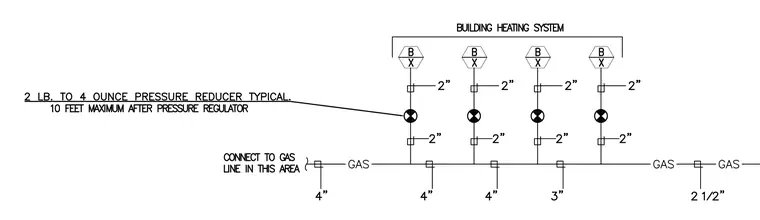
This diagram details the gas distribution piping layout for a building heating system, featuring a main gas line branching into four boiler connections. The system incorporates two-inch branch lines with valves and a two pound to four ounce pressure reducer typical, maintaining a ten foot maximum distance after the pressure regulator. Branch line pipe sizes are specified at two inches with main header sizes ranging from two and one-half to four inches.
Members view this detail in full resolution, download the CAD files (SVG, PDF), and can adapt it in the built-in CAD editor — export DXF, DWG, or PDF.
Start membership