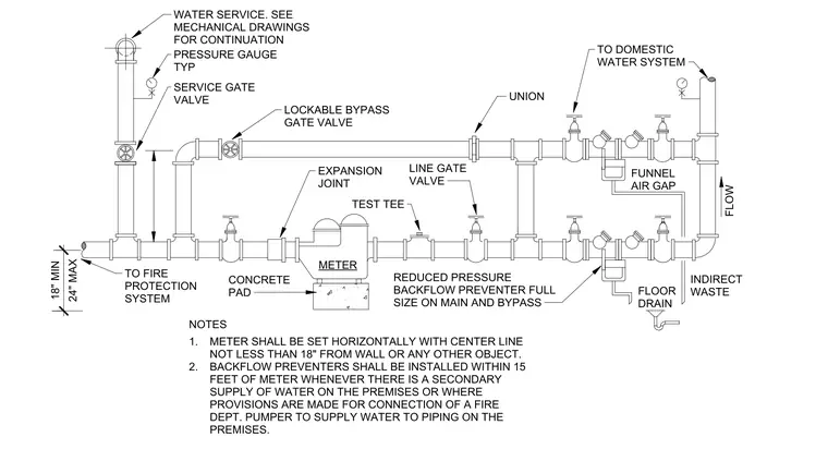
The water service line connects to a service gate valve and branches into a metered main line and a lockable bypass gate valve. A reduced pressure backflow preventer is installed downstream of the meter, complete with test tees, unions, and line gate valves. The meter rests on a concrete pad, with an expansion joint positioned upstream. Relief valve discharges and indirect waste lines route through funnels to floor drains. Pressure gauges are located at typical intervals throughout the piping arrangement.
NOTES FLOW UNION TEST TEE METER TO DOMESTIC WATER SYSTEM FUNNEL AIR GAP INDIRECT WASTE FLOOR DRAIN 1. 2. METER SHALL BE SET HORIZONTALLY WITH CENTER LINE NOT LESS THAN 18" FROM WALL OR ANY OTHER OBJECT. BACKFLOW PREVENTERS SHALL BE INSTALLED WITHIN 15 FEET OF METER WHENEVER THERE IS A SECONDARY SUPPLY OF WATER ON THE PREMISES OR WHERE PROVISIONS ARE MADE FOR CONNECTION OF A FIRE DEPT. PUMPER TO SUPPLY WATER TO PIPING ON THE PREMISES. REDUCED PRESSURE BACKFLOW PREVENTER FULL SIZE ON MAIN AND BYPASS LINE GATE VALVE EXPANSION JOINT CONCRETE PAD TO FIRE PROTECTION SYSTEM LOCKABLE BYPASS GATE VALVE SERVICE GATE VALVE PRESSURE GAUGE TYP WATER SERVICE. SEE MECHANICAL DRAWINGS FOR CONTINUATION 24" MAX 18" MIN
Members view this detail in full resolution, download the CAD files (SVG, PDF), and can adapt it in the built-in CAD editor — export DXF, DWG, or PDF.
Start membership