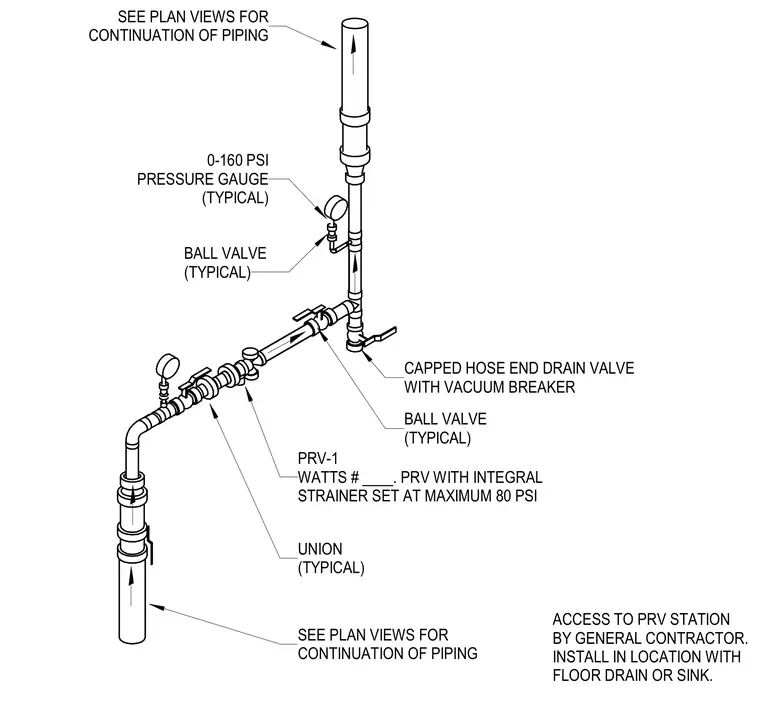
A single pressure reducing valve station includes a pressure-reducing valve with an integral strainer set at a maximum of eighty pounds per square inch, flanked by typical unions and ball valves for isolation. Typical zero to one hundred sixty pounds per square inch pressure gauges are installed upstream and downstream of the assembly. A capped hose end drain valve with a vacuum breaker is provided for maintenance draining. The entire assembly requires access by the general contractor in a location with a floor drain or sink, with piping continuing to plan views.
BALL VALVE (TYPICAL) ACCESS TO PRV STATION BY GENERAL CONTRACTOR. INSTALL IN LOCATION WITH FLOOR DRAIN OR SINK. CAPPED HOSE END DRAIN VALVE WITH VACUUM BREAKER BALL VALVE (TYPICAL) PRV-1 WATTS # ____. PRV WITH INTEGRAL STRAINER SET AT MAXIMUM 80 PSI UNION (TYPICAL) SEE PLAN VIEWS FOR CONTINUATION OF PIPING SEE PLAN VIEWS FOR CONTINUATION OF PIPING 0-160 PSI PRESSURE GAUGE (TYPICAL)
Members view this detail in full resolution, download the CAD files (SVG, PDF), and can adapt it in the built-in CAD editor — export DXF, DWG, or PDF.
Start membership