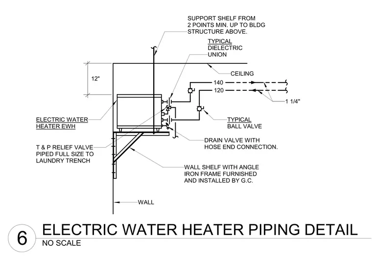
An electric water heater is supported on a wall-mounted shelf featuring an angle iron frame furnished and installed by the general contractor, with additional structural support hung from two points minimum up to the building structure above. The unit is connected to one and one-quarter inch water supply piping utilizing typical dielectric unions and typical ball valves. A temperature and pressure relief valve is piped at full size directly to a laundry trench, while a drain valve with a hose end connection is installed near the bottom. A twelve-inch clearance is maintained between the top of the heater and the ceiling.
DRAIN VALVE WITH HOSE END CONNECTION. SUPPORT SHELF FROM 2 POINTS MIN. UP TO BLDG STRUCTURE ABOVE. TYPICAL BALL VALVE WALL SHELF WITH ANGLE IRON FRAME FURNISHED AND INSTALLED BY G.C. ELECTRIC WATER HEATER EWH T & P RELIEF VALVE PIPED FULL SIZE TO LAUNDRY TRENCH 12" WALL TYPICAL DIELECTRIC UNION CEILING 1 1/4" 120 140 NO SCALE 6 ELECTRIC WATER HEATER PIPING DETAIL
Members view this detail in full resolution, download the CAD files (SVG, PDF), and can adapt it in the built-in CAD editor — export DXF, DWG, or PDF.
Start membership