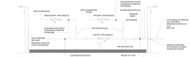
Incoming six-inch domestic cold water line enters the building through a sleeve or core-drill equipped with a water-tight link-seal system. The piping layout incorporates a building isolation valve, pressure gauge, and wye strainer before routing through a backflow preventer sized per schedule. Additional flow meters with building automation system outputs are integrated along the domestic cold water, irrigation, and rainwater system lines. Pipe sizes and routing follow the architectural and plumbing plans, maintaining specific clearance heights above finished floors.
18" MIN. 30" MAX. WYE STRAINER PIPE SIZE PER PLANS 6" DCW FROM CITY METER BY CIVIL. SEE PIPING SPECIFICATION FOR D.C.W. (U.G) PIPE TYPE PRESSURE GAUGE FLOW METER WITH OUTPUT BUILDING ISOLATION VALVE SLEEVE OR CORE-DRILL WITH LINK-SEAL OR EQUAL WATER-TIGHT SYSTEM DCW TO BUILDING. SEE PLANS M M M DCW BFP - PER SCHEDULE NPCW BFP - PER SCHEDULE IRRIGATION BFP - PER SCHEDULE NPCW TO IRRIGATION NPCW TO RAINWATER SYSTEM PIPE SIZE PER PLANS REFERENCE PLANS FOR ACTUAL DCW ROUTING. FLOW METER WITH OUTPUT TO BUILDING AUTOMATION SYSTEM (BAS) FLOW METER WITH OUTPUT TO BUILDING AUTOMATION SYSTEM (BAS) REDUCE TO 4" DCW
Members view this detail in full resolution, download the CAD files (SVG, PDF), and can adapt it in the built-in CAD editor — export DXF, DWG, or PDF.
Start membership