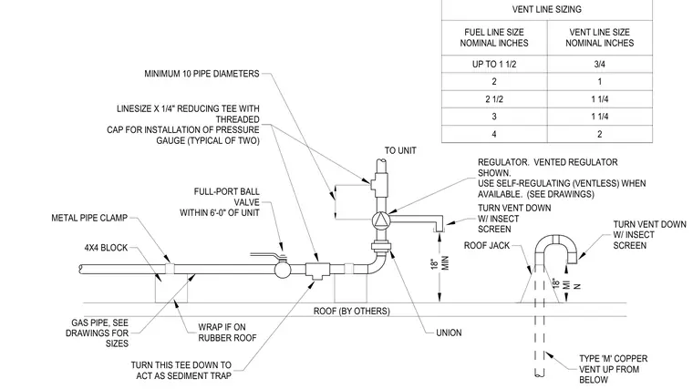
Natural gas service piping routes across the roof supported by four-by-four wood blocks and metal pipe clamps, wrapping the pipe when installed on a rubber roof. A full-port ball valve is positioned within six feet of the mechanical unit, followed by a reducing tee oriented downward to act as a sediment trap. A vented gas pressure regulator connects ahead of the unit with upstream and downstream pressure gauge test connections spaced a minimum of ten pipe diameters apart. A separate Type M copper vent line extends up from below through a roof jack, terminating with a downward turn and an insect screen eighteen inches minimum above the roof surface.
2 1/2 FUEL LINE SIZE NOMINAL INCHES UP TO 1 1/2 3 4 2 1 1/4 2 1 1/4 VENT LINE SIZE NOMINAL INCHES 3/4 1 VENT LINE SIZING TO UNIT 18" MIN 18" MI N ROOF (BY OTHERS) TURN VENT DOWN W/ INSECT SCREEN TURN VENT DOWN W/ INSECT SCREEN REGULATOR. VENTED REGULATOR SHOWN. USE SELF-REGULATING (VENTLESS) WHEN AVAILABLE. (SEE DRAWINGS) UNION ROOF JACK TURN THIS TEE DOWN TO ACT AS SEDIMENT TRAP GAS PIPE, SEE DRAWINGS FOR SIZES 4X4 BLOCK METAL PIPE CLAMP FULL-PORT BALL VALVE WITHIN 6'-0" OF UNIT LINESIZE X 1/4" REDUCING TEE WITH THREADED CAP FOR INSTALLATION OF PRESSURE GAUGE (TYPICAL OF TWO) MINIMUM 10 PIPE DIAMETERS WRAP IF ON RUBBER ROOF TYPE 'M' COPPER VENT UP FROM BELOW
Members view this detail in full resolution, download the CAD files (SVG, PDF), and can adapt it in the built-in CAD editor — export DXF, DWG, or PDF.
Start membership