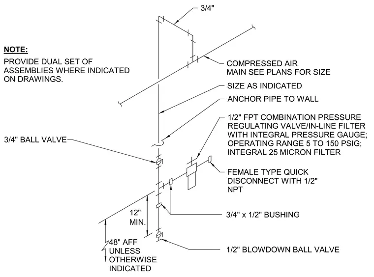
A compressed air drop connects to a main line sized per plans. The vertical drop features a three-quarter-inch ball valve and transitions via a three-quarter-inch by one-half-inch bushing to a one-half-inch female pipe thread combination pressure regulating valve and in-line filter with an integral pressure gauge. The regulating valve operates within a range of five to one hundred fifty pounds per square inch gauge and includes an integral twenty-five micron filter. A female type quick disconnect with a one-half-inch national pipe thread branches off the valve assembly, and a one-half-inch blowdown ball valve is positioned at the bottom of the drop at least twelve inches above a finished floor height of forty-eight inches unless otherwise indicated. The pipe drop is anchored securely to the adjacent wall, and dual sets of assemblies are provided where indicated on the drawings.
MIN. 12" NOTE: ANCHOR PIPE TO WALL 3/4" x 1/2" BUSHING 1/2" BLOWDOWN BALL VALVE SIZE AS INDICATED FEMALE TYPE QUICK DISCONNECT WITH 1/2" NPT 48" AFF UNLESS OTHERWISE INDICATED PROVIDE DUAL SET OF ASSEMBLIES WHERE INDICATED ON DRAWINGS. 1/2" FPT COMBINATION PRESSURE REGULATING VALVE/IN-LINE FILTER WITH INTEGRAL PRESSURE GAUGE; OPERATING RANGE 5 TO 150 PSIG; INTEGRAL 25 MICRON FILTER COMPRESSED AIR MAIN SEE PLANS FOR SIZE 3/4" BALL VALVE 3/4"
Members view this detail in full resolution, download the CAD files (SVG, PDF), and can adapt it in the built-in CAD editor — export DXF, DWG, or PDF.
Start membership