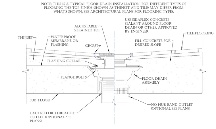
The floor drain assembly rests within a concrete sub-floor, topped with fill concrete shaped to achieve the desired slope toward the adjustable strainer top. A waterproof membrane or flashing is installed beneath the thinset layer supporting the tile flooring. A flashing collar is secured with flange bolts to the drain body. A grout bed surrounds the strainer flange, and Sikaflex concrete sealant or an approved equivalent is applied around the perimeter of the drain. The outlet connects via a no-hub band or a caulked or threaded connection as specified on the plumbing plans.
NO HUB BAND OUTLET (OPTIONAL SEE PLANS) CAULKED OR THREADED OUTLET (OPTIONAL SEE PLANS) ADJUSTABLE STRAINER TOP FILL CONCRETE FOR DESIRED SLOPE THINSET WATERPROOF MEMBRANE OR FLASHING GROUT FLANGE BOLTS SUB-FLOOR FLOOR DRAIN ASSEMBLY FLASHING COLLAR USE SIKAFLEX CONCRETE SEALANT AROUND FLOOR DRAIN OR OTHER APPROVED BY ENGINEER. TILE FLOORING NOTE: THIS IS A TYPICAL FLOOR DRAIN INSTALLATION. FOR DIFFERENT TYPES OF FLOORING THE TOP FINISH (SHOWN AS THINSET AND TILE) MAY DIFFER FROM WHAT'S SHOWN. SEE ARCHITECTURAL PLANS FOR FLOORING TYPES.
Members view this detail in full resolution, download the CAD files (SVG, PDF), and can adapt it in the built-in CAD editor — export DXF, DWG, or PDF.
Start membership