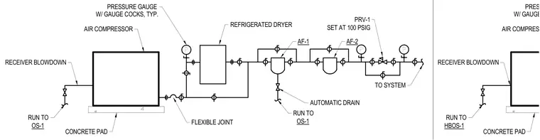
An air compressor rests on a concrete pad with a receiver blowdown line running to OS-1 and an adjacent pressure gauge equipped with gauge cocks. A flexible joint isolates the compressor discharge before entering a refrigerated dryer. The piping continues through inline filters AF-1 and AF-2, each with an automatic drain running to OS-1. Downstream of the filtration, a pressure-reducing valve set at 100 PSIG regulates supply pressure ahead of the final pressure gauge and distribution connection to the system.
P P P RUN TO OS-1 TO SYSTEM AF-2 AF-1 REFRIGERATED DRYER AIR COMPRESSOR CONCRETE PAD AUTOMATIC DRAIN RUN TO RECEIVER BLOWDOWN OS-1 FLEXIBLE JOINT PRESSURE GAUGE W/ GAUGE COCKS, TYP. PRV-1 SET AT 100 PSIG AIR COMPRESSOR CONCRETE PAD RUN TO RECEIVER BLOWDOWN HBOS-1 PRESSURE GAUGE W/ GAUGE COCKS, TYP.
Members view this detail in full resolution, download the CAD files (SVG, PDF), and can adapt it in the built-in CAD editor — export DXF, DWG, or PDF.
Start membership