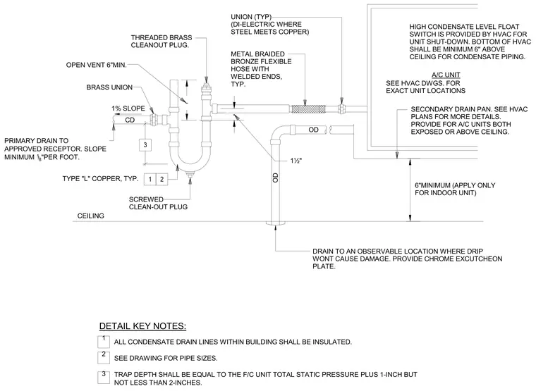
Condensate piping connects to the fan coil unit via a metal braided bronze flexible hose with welded ends and a di-electric union where steel meets copper. The primary drain line incorporates a trap with a threaded brass cleanout plug, a minimum trap depth equal to the unit total static pressure plus one inch but not less than two inches, an open vent of six inches minimum, and a brass union. Piping slopes at one percent or a minimum of one-eighth inch per foot to an approved receptor with all interior condensate lines insulated. A secondary drain line routes from the secondary drain pan through the ceiling to an observable location with a chrome escutcheon plate. The bottom of the HVAC unit maintains a six-inch minimum clearance above the ceiling for condensate piping access.
CEILING ALL CONDENSATE DRAIN LINES WITHIN BUILDING SHALL BE INSULATED. SEE DRAWING FOR PIPE SIZES. TRAP DEPTH SHALL BE EQUAL TO THE F/C UNIT TOTAL STATIC PRESSURE PLUS 1-INCH BUT NOT LESS THAN 2-INCHES. THREADED BRASS CLEANOUT PLUG. OPEN VENT 6"MIN. TYPE "L" COPPER, TYP. METAL BRAIDED BRONZE FLEXIBLE HOSE WITH WELDED ENDS, TYP. DRAIN TO AN OBSERVABLE LOCATION WHERE DRIP WONT CAUSE DAMAGE. PROVIDE CHROME EXCUTCHEON PLATE. SECONDARY DRAIN PAN. SEE HVAC PLANS FOR MORE DETAILS. PROVIDE FOR A/C UNITS BOTH EXPOSED OR ABOVE CEILING. SCREWED CLEAN-OUT PLUG HIGH CONDENSATE LEVEL FLOAT SWITCH IS PROVIDED BY HVAC FOR UNIT SHUT-DOWN. BOTTOM OF HVAC SHALL BE MINIMUM 6" ABOVE CEILING FOR CONDENSATE PIPING. 6"MINIMUM (APPLY ONLY FOR INDOOR UNIT) BRASS UNION PRIMARY DRAIN TO APPROVED RECEPTOR. SLOPE MINIMUM 1 /8 "PER FOOT. 1½" UNION (TYP) (DI-ELECTRIC WHERE STEEL MEETS COPPER) CD OD OD DETAIL KEY NOTES: 3 2 1 3 2 1 1% SLOPE - - SEE HVAC DWGS. FOR EXACT UNIT LOCATIONS A/C UNIT
Members view this detail in full resolution, download the CAD files (SVG, PDF), and can adapt it in the built-in CAD editor — export DXF, DWG, or PDF.
Start membership