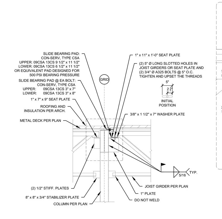
An expansion joint assembly occurs at a joist girder and column support per plan. A 1-inch by 11-inch by 1-foot-0-inch seat plate and a 1-inch by 7-inch by 9-inch seat plate are supported by an 8-inch by 8-inch by 3/4-inch stabilizer plate and two 1/2-inch stiffener plates. A slide bearing pad by Con-Serv, Type CSA, with upper and lower dimensions of 9-1/2 inches by 11-1/2 inches, is designed for 500 PSI bearing pressure. Two 5-inch diameter long slotted holes in the joist girders or seat plate accommodate two 3/4-inch diameter A325 bolts at 5 inches on center with tightened and upset threads. Additional slide bearing pads measuring 3 inches by 7 inches upper and 3 inches by 8 inches lower are provided at each bolt along with a 3/8-inch by 1-1/2-inch by 7-inch washer plate. Five-sixteenths inch typical fillet welds secure the connection while leaving the plate left unwelded to the girder as noted. Metal deck, roofing, and insulation are installed per architectural drawings.
GRID COLUMN PER PLAN 8" x 8" x 3/4" STABILIZER PLATE JOIST GIRDER PER PLAN ROOFING AND INSULATION PER ARCH. METAL DECK PER PLAN DO NOT WELD 1" x 7" x 9" SEAT PLATE (2) 1/2" STIFF. PLATES 1" x 11" x 1'-0" SEAT PLATE 1" PLATE 5/16 TYP. 3/8" x 1 1/2" x 7" WASHER PLATE SLIDE BEARING PAD: CON-SERV, TYPE CSA UPPER: 09CSA 13CS 9 1/2" x 11 1/2" LOWER: 09CSA 13CS 6 1/2" x 11 1/2" OR EQUIVALENT PAD DESIGNED FOR 500 PSI BEARING PRESSURE (2) 5" Ø LONG SLOTTED HOLES IN JOIST GIRDERS OR SEAT PLATE AND (2) 3/4" Ø A325 BOLTS @ 5" O.C. TIGHTEN AND UPSET THE THREADS SLIDE BEARING PAD @ EA BOLT: CON-SERV, TYPE CSA UPPER: 09CSA 13CS 3" x 7" LOWER: 09CSA 13CS 3" x 8" 5" 2 1 2 " INITIAL POSITION 1'-0" 0'-1"
Members view this detail in full resolution, download the CAD files (SVG, PDF), and can adapt it in the built-in CAD editor — export DXF, DWG, or PDF.
Start membership