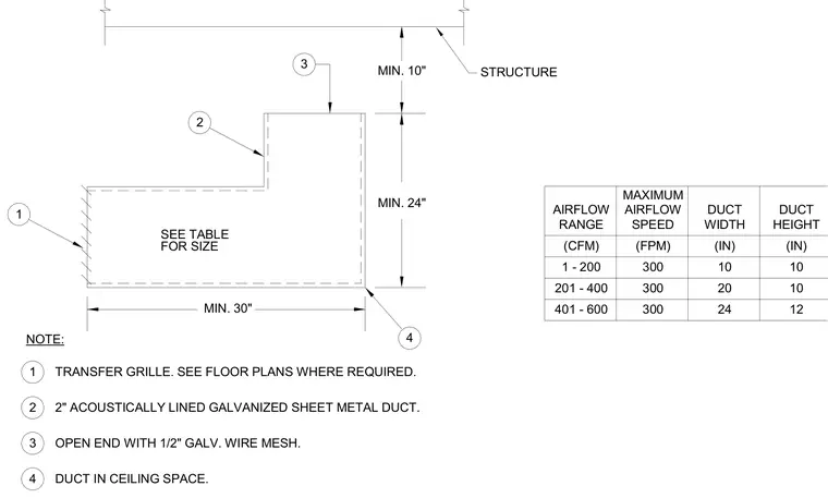
The assembly consists of a two-inch acoustically lined galvanized sheet metal duct installed within the ceiling space below the structure. A transfer grille is located at one end per the floor plans, while the opposite open end is fitted with a one-half-inch galvanized wire mesh. Minimum clearances include ten inches from the structure and a thirty-inch duct width with a twenty-four-inch height. Sizing is determined by airflow range, maximum airflow speed, duct width, and duct height according to the provided table.
STRUCTURE MIN. 10" DUCT HEIGHT (IN) 10 10 12 DUCT WIDTH (IN) 10 20 24 MAXIMUM AIRFLOW SPEED (FPM) 300 300 300 AIRFLOW RANGE (CFM) 1 - 200 201 - 400 401 - 600 FOR SIZE SEE TABLE 1 2 3 4 MIN. 30" MIN. 24" DUCT IN CEILING SPACE. 4 OPEN END WITH 1/2" GALV. WIRE MESH. 3 TRANSFER GRILLE. SEE FLOOR PLANS WHERE REQUIRED. 2" ACOUSTICALLY LINED GALVANIZED SHEET METAL DUCT. 2 NOTE: 1
Members view this detail in full resolution, download the CAD files (SVG, PDF), and can adapt it in the built-in CAD editor — export DXF, DWG, or PDF.
Start membership