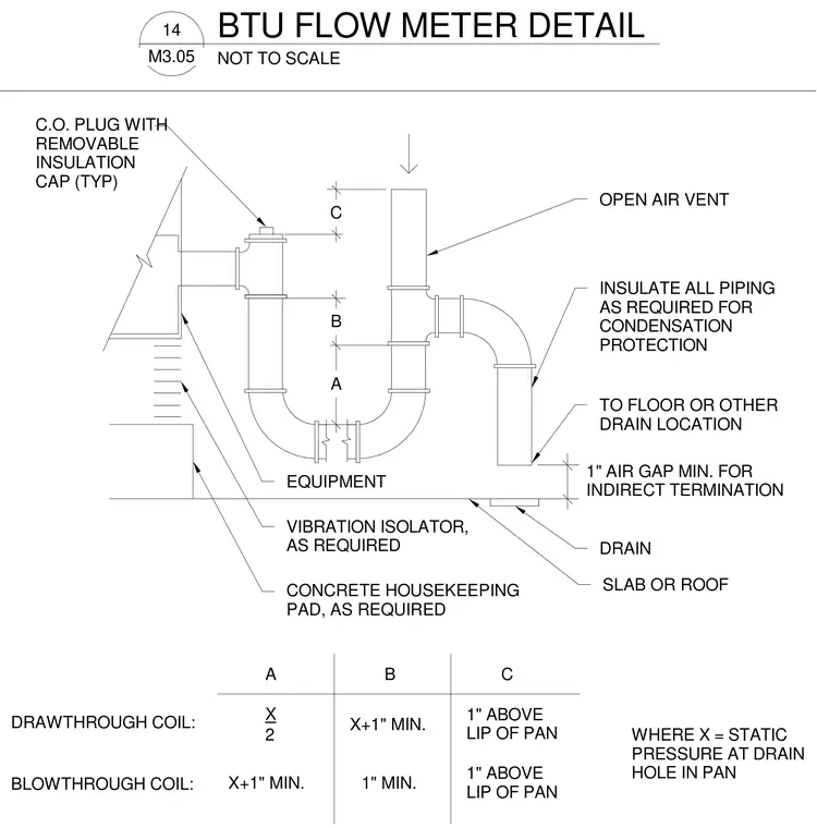
A condensate drain trap assembly connects to equipment resting on a concrete housekeeping pad with vibration isolators. The piping features a cleanout plug with a removable insulation cap and an open air vent. A sizing table defines dimensions A, B, and C based on static pressure for draw-through and blow-through coil configurations. All piping is insulated as required for condensation protection and terminates with a minimum one-inch air gap above a drain location on a slab or roof.
BTU FLOW METER DETAIL 14 M3.05 NOT TO SCALE A B WHERE X = STATIC PRESSURE AT DRAIN HOLE IN PAN X 2 A X+1" MIN. B DRAWTHROUGH COIL: 1" MIN. BLOWTHROUGH COIL: X+1" MIN. C 1" ABOVE LIP OF PAN C 1" ABOVE LIP OF PAN 1" AIR GAP MIN. FOR INDIRECT TERMINATION C.O. PLUG WITH REMOVABLE INSULATION CAP (TYP) INSULATE ALL PIPING AS REQUIRED FOR CONDENSATION PROTECTION TO FLOOR OR OTHER DRAIN LOCATION DRAIN SLAB OR ROOF VIBRATION ISOLATOR, AS REQUIRED CONCRETE HOUSEKEEPING PAD, AS REQUIRED EQUIPMENT OPEN AIR VENT
Members view this detail in full resolution, download the CAD files (SVG, PDF), and can adapt it in the built-in CAD editor — export DXF, DWG, or PDF.
Start membership