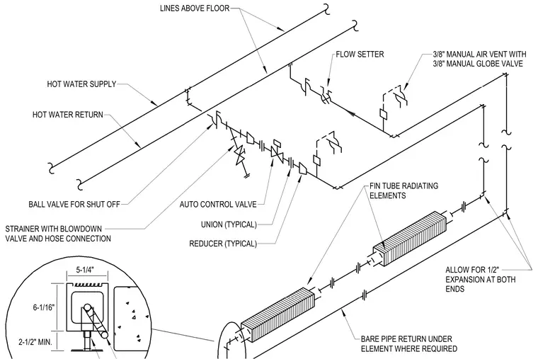
This isometric and sectional schematic details the piping configuration for pedestal-type fin-tube radiating elements connected to hot water supply and return lines above the floor. The system incorporates a three-eighths-inch manual air vent with a three-eighths-inch manual globe valve, flow setters, shut-off ball valves, and a strainer equipped with a blowdown valve and hose connection. An automatic control valve regulates flow, while typical unions and reducers accommodate pipe sizing transitions. A bare pipe return runs beneath the element where required, and piping is installed with a minimum two-and-a-half-inch clearance and allowance for half-inch thermal expansion at both ends.
3/8" MANUAL AIR VENT WITH 3/8" MANUAL GLOBE VALVE FLOW SETTER LINES ABOVE FLOOR HOT WATER SUPPLY HOT WATER RETURN BALL VALVE FOR SHUT OFF STRAINER WITH BLOWDOWN VALVE AND HOSE CONNECTION AUTO CONTROL VALVE UNION (TYPICAL) REDUCER (TYPICAL) FIN TUBE RADIATING ELEMENTS BARE PIPE RETURN UNDER ELEMENT WHERE REQUIRED ALLOW FOR 1/2" EXPANSION AT BOTH ENDS 2-1/2" MIN. 6-1/16" 5-1/4"
Members view this detail in full resolution, download the CAD files (SVG, PDF), and can adapt it in the built-in CAD editor — export DXF, DWG, or PDF.
Start membership