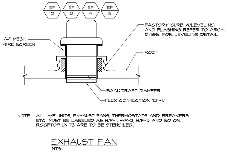
An exhaust fan penetrates the roof assembly through a factory curb with leveling and flashing, coordinated with architectural drawings for the leveling detail. A one-quarter-inch mesh wire screen surrounds the upper portion of the exhaust fan assembly. A backdraft damper and a flexible connection labeled EF-1 install directly below the roof line. General notes require all heat pump units, exhaust fans, thermostats, and breakers to be labeled sequentially as H/P-1, H/P-2, H/P-3 and so on, with rooftop units requiring stenciling.
Members view this detail in full resolution, download the CAD files (SVG, PDF), and can adapt it in the built-in CAD editor — export DXF, DWG, or PDF.
Start membership