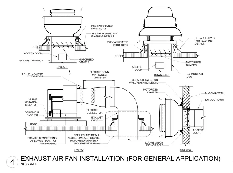
The installation assembly consists of pre-fabricated roof curbs supporting upblast and downblast exhaust fans, complete with motorized dampers, access doors, and exhaust air ducts. Flexible connectors join utility fan setups to ductwork, mounted on equipment base rails with spring vibration isolators. Sidewall exhaust configurations anchor directly to masonry walls using expansion or anchor bolts and include sheet metal covers at top edges. Roof penetrations require architectural flashing details and drain fittings installed at the lowest point of the fan housing.
SEE ARCH. DWG. FOR FLASHING DETAILS MOTORIZED DAMPER EXHAUST AIR DUCT ACCESS DOOR MASONRY WALL SEE ARCH. DWG. FOR WALL FLASHING DETAIL EXHAUST DUCT ACCESS DOOR MOTORIZED DAMPER EXPANSION OR ANCHOR BOLT FLEXIBLE CONNECTOR SEE UPBLAST DETAIL ABOVE- SIMILAR. PROVIDE MOTORIZED DAMPER AT ROOF PENETRATION PROVIDE DRAIN FITTING AT LOWEST POINT OF FAN HOUSING ROOF EQUIPMENT BASE RAIL SPRING VIBRATION ISOLATOR SHT. MTL. COVER AT TOP EDGE EXHAUST AIR DUCT ACCESS DOOR ROOF MOTORIZED DAMPER SEE ARCH. DWG. FOR FLASHING DETAILS PRE-FABRICATED ROOF CURB PRE-FABRICATED ROOF CURB ROOF EXHAUST DUCT UPBLAST DOWNBLAST SIDE WALL UTILITY FLEXIBLE CONN. MIN. 3XINLET DIAMETER NO SCALE 4 EXHAUST AIR FAN INSTALLATION (FOR GENERAL APPLICATION)
Members view this detail in full resolution, download the CAD files (SVG, PDF), and can adapt it in the built-in CAD editor — export DXF, DWG, or PDF.
Start membership