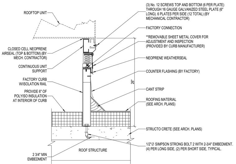
A rooftop unit is supported by a twenty-six-inch-high factory curb equipped with an isolation rail and six inches of polyiso insulation at the interior. The rooftop unit connects to the continuous unit support using three number twelve screws top and bottom through six-inch-long sixteen-gauge galvanized steel plates, with twelve total plates per unit provided by the mechanical contractor. Closed-cell neoprene airseals are positioned at the top and bottom of the support, alongside a removable sheet metal cover for adjustment and inspection provided by the curb manufacturer. Neoprene weatherseals and factory-provided counter flashing interface with the cant strip and roofing material over structural concrete. The curb anchors to the roof structure using one-half-inch diameter Simpson Strong-Bolt 2 anchors with two-and-three-quarter-inch minimum embedment, configured with four per long side and two per short side.
ROOFTOP UNIT (3) No. 12 SCREWS TOP AND BOTTOM (6 PER PLATE) THROUGH 16 GAUGE GALVANIZED STEEL PLATE (6" LONG). 6 PLATES PER SIDE (12 TOTAL) (BY MECHANICAL CONTRACTOR) FACTORY CONNECTION **REMOVABLE SHEET METAL COVER FOR ADJUSTMENT AND INSPECTION (PROVIDED BY CURB MANUFACTURER) NEOPRENE WEATHERSEAL COUNTER FLASHING (BY FACTORY) CANT STRIP ROOFING MATERIAL (SEE ARCH. PLANS) STRUCTO CRETE (SEE ARCH. PLANS) 1/2" ∅ SIMPSON STRONG BOLT 2 WITH 2-3/4" EMBEDMENT. (4) PER LONG SIDE, (2) PER SHORT SIDE, TYPICAL. 2 3/4" MIN EMBEDMENT ROOF STRUCTURE CLOSED CELL NEOPRENE AIRSEAL (TOP & BOTTOM) (BY MECH. CONTRACTOR) CONTINUOUS UNIT SUPPORT FACTORY CURB W/ISOLATION RAIL 26" PROVIDE 6" OF POLYISO INSULATION AT INTERIOR OF CURB /^n / _ ~~ y/ / / / / / -"•V //// l t ■v / sm ■v- zl <7 " £
Members view this detail in full resolution, download the CAD files (SVG, PDF), and can adapt it in the built-in CAD editor — export DXF, DWG, or PDF.
Start membership