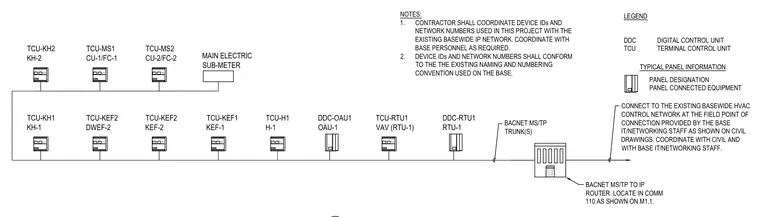
Direct digital control system schematic diagram showing HVAC terminal units and BACnet MS/TP network connections. The system links terminal control units, rooftop units, and equipment controllers to a BACnet MS/TP to IP router located in communication room 110. The network connects to the existing basewide HVAC control network at the field point of connection provided by base IT and networking staff. Contractor coordinates device IDs and network numbers with the existing basewide IP network and base personnel according to established naming conventions.
LEGEND TYPICAL PANEL INFORMATION DDC TCU DIGITAL CONTROL UNIT TERMINAL CONTROL UNIT CONNECT TO THE EXISTING BASEWIDE HVAC CONTROL NETWORK AT THE FIELD POINT OF CONNECTION PROVIDED BY THE BASE IT/NETWORKING STAFF AS SHOWN ON CIVIL DRAWINGS. COORDINATE WITH CIVIL AND WITH BASE IT/NETWORKING STAFF. PANEL DESIGNATION PANEL CONNECTED EQUIPMENT BACNET MS/TP TO IP ROUTER. LOCATE IN COMM 110 AS SHOWN ON M1.1. DDC-RTU1 RTU-1 TCU-RTU1 VAV (RTU-1) DDC-OAU1 OAU-1 TCU-KEF1 KEF-1 TCU-KEF2 KEF-2 TCU-KH1 KH-1 TCU-MS1 CU-1/FC-1 TCU-MS2 CU-2/FC-2 TCU-KEF2 DWEF-2 TCU-KH2 KH-2 TCU-H1 H-1 NOTES: 1. CONTRACTOR SHALL COORDINATE DEVICE IDs AND NETWORK NUMBERS USED IN THIS PROJECT WITH THE EXISTING BASEWIDE IP NETWORK. COORDINATE WITH BASE PERSONNEL AS REQUIRED. 2. DEVICE IDs AND NETWORK NUMBERS SHALL CONFORM TO THE THE EXISTING NAMING AND NUMBERING CONVENTION USED ON THE BASE. MAIN ELECTRIC SUB-METER BACNET MS/TP TRUNK(S)
Members view this detail in full resolution, download the CAD files (SVG, PDF), and can adapt it in the built-in CAD editor — export DXF, DWG, or PDF.
Start membership