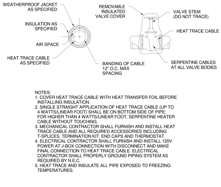
Heat trace cables are wrapped or banded to the piping system to prevent freezing in exposed locations. A single straight application of heat trace cable up to four watts per linear foot is placed on the bottom side of the pipe, while higher ratings require serpentine heater cable configurations without touching. Heat transfer foil covers the cable prior to installing the specified insulation and weatherproof jacket. Cable banding is spaced at a maximum of twelve inches on center, and serpentine cables are applied at all valve bodies with a removable insulated valve cover left untraced around the valve stem. The mechanical contractor furnishes and installs the cable and accessories while the electrical contractor provides power and grounding.
NOTES: 1. COVER HEAT TRACE CABLE WITH HEAT TRANSFER FOIL BEFORE INSTALLING INSULATION. 2. SINGLE STRAIGHT APPLICATION OF HEAT TRACE CABLE (UP TO 4 WATTS/LINEAR FOOT) SHALL BE ON BOTTOM SIDE OF PIPE; FOR HIGHER THAN 4 WATTS/LINEAR FOOT, SERPENTINE HEATER CABLE WITHOUT TOUCHING. 3. MECHANICAL CONTRACTOR SHALL FURNISH AND INSTALL HEAT TRACE CABLE AND ALL REQUIRED ACCESSORIES INCLUDING T-SPLICES, TERMINATION KIT, END CAPS AND THERMOSTAT. 4. ELECTRICAL CONTRACTOR SHALL FURNISH AND INSTALL 120V POWER AT J-BOX CONNECTION WITH DISCONNECT AND MAKE FINAL CONNECTION TO HEAT TRACE CABLE. ELECTRICAL CONTRACTOR SHALL PROPERLY GROUND PIPING SYSTEM AS REQUIRED BY N.E.C. 5. HEAT TRACE AND INSULATE ALL PIPE EXPOSED TO FREEZING TEMPERATURES. REMOVABLE INSULATED VALVE COVER VALVE STEM (DO NOT TRACE) HEAT TRACE CABLE SERPENTINE CABLES AT ALL VALVE BODIES BANDING OF CABLE 12" O.C. MAX SPACING AIR SPACE HEAT TRACE CABLE AS SPECIFIED INSULATION AS SPECIFIED WEATHERPROOF JACKET AS SPECIFIED
Members view this detail in full resolution, download the CAD files (SVG, PDF), and can adapt it in the built-in CAD editor — export DXF, DWG, or PDF.
Start membership