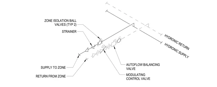
A hydronic control valve assembly connects the main supply and return headers to a heating or cooling zone. The supply branch includes a strainer, two typical zone isolation ball valves, an autoflow balancing valve, and a modulating control valve. The piping routes conditioned fluid from the hydronic supply to the zone and returns it through the hydronic return loop.
HYDRONIC RETURN HYDRONIC SUPPLY STRAINER SUPPLY TO ZONE RETURN FROM ZONE MODULATING CONTROL VALVE AUTOFLOW BALANCING VALVE ZONE ISOLATION BALL VALVES (TYP 2)
Members view this detail in full resolution, download the CAD files (SVG, PDF), and can adapt it in the built-in CAD editor — export DXF, DWG, or PDF.
Start membership