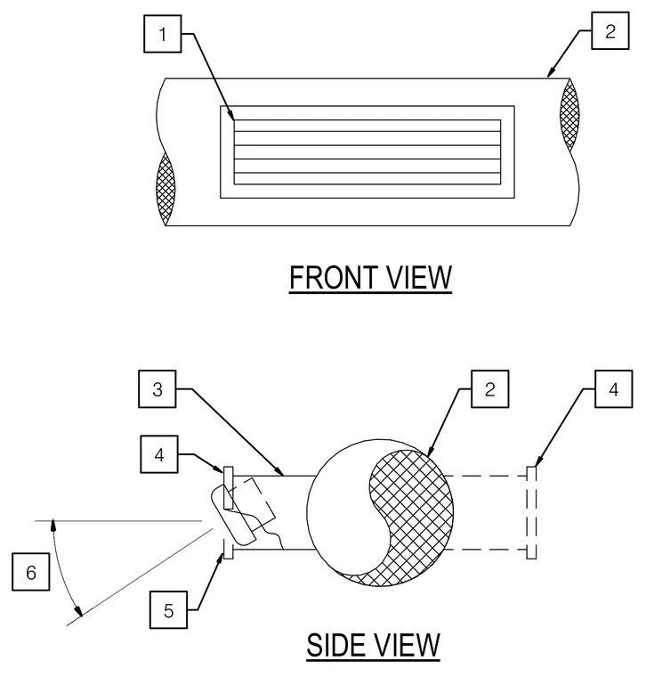
The assembly features a primary cylindrical member fitted with a slotted component and multiple mounting or alignment plates connected around the central profile. Numbered reference callouts indicate specific constituent parts, including a slotted central insert and angled adjustment boundaries denoted by an angular dimension indicator. The layout provides front and side orthographic projections of the mechanical part configuration.
Members view this detail in full resolution, download the CAD files (SVG, PDF), and can adapt it in the built-in CAD editor — export DXF, DWG, or PDF.
Start membership