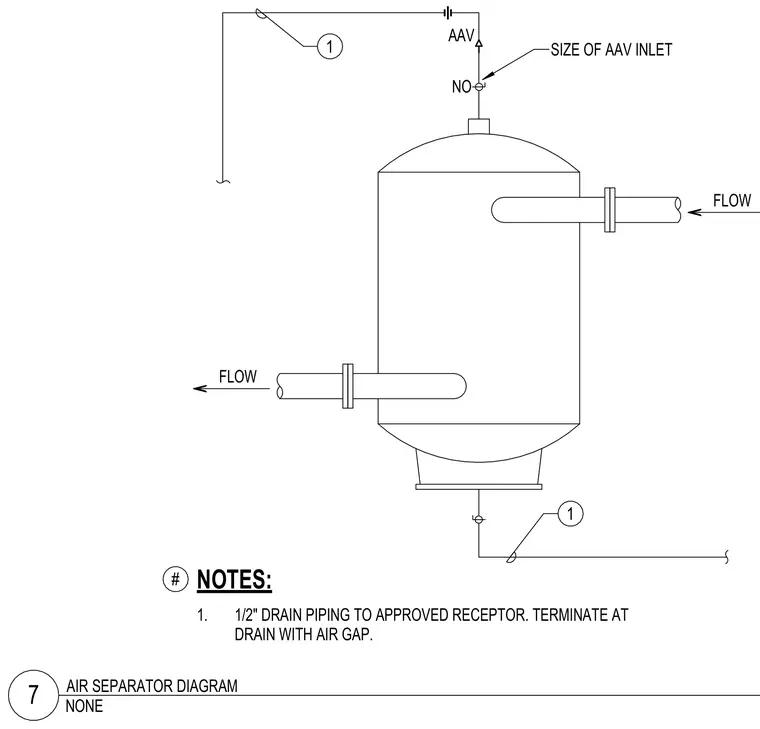
An air separator unit features flanged inlet and outlet piping connections for fluid flow. An air admittance valve connects to the top of the vessel, sized per the inlet requirement. Half-inch drain piping routes from the bottom and top to an approved receptor with a required air gap.
1. 1/2" DRAIN PIPING TO APPROVED RECEPTOR. TERMINATE AT DRAIN WITH AIR GAP. NOTES: # 1 1 SIZE OF AAV INLET FLOW FLOW AAV NO NONE 7 AIR SEPARATOR DIAGRAM HE A -e 1 o C -c : : l e- o
Members view this detail in full resolution, download the CAD files (SVG, PDF), and can adapt it in the built-in CAD editor — export DXF, DWG, or PDF.
Start membership