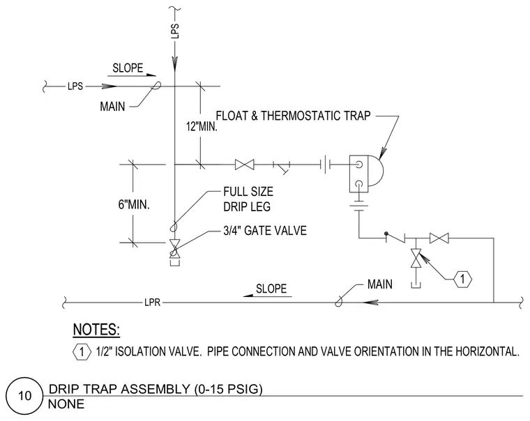
A drip trap assembly operates on low-pressure steam from zero to fifteen psig. A full-size drip leg extends twelve inches minimum below the main line drop, terminating in a three-quarter inch gate valve. The line connects to a float and thermostatic trap with a six-inch minimum clearance from the lower return piping. Pipe connections and valve orientations are maintained in the horizontal plane with a one-half inch isolation valve.
LPS LPS LPR SLOPE SLOPE NOTES: NOTES: MAIN MAIN FLOAT & THERMOSTATIC TRAP 6"MIN. FULL SIZE DRIP LEG 12"MIN. 3/4" GATE VALVE 1 1/2" ISOLATION VALVE. PIPE CONNECTION AND VALVE ORIENTATION IN THE HORIZONTAL. 1 NONE 10 DRIP TRAP ASSEMBLY (0-15 PSIG)
Members view this detail in full resolution, download the CAD files (SVG, PDF), and can adapt it in the built-in CAD editor — export DXF, DWG, or PDF.
Start membership