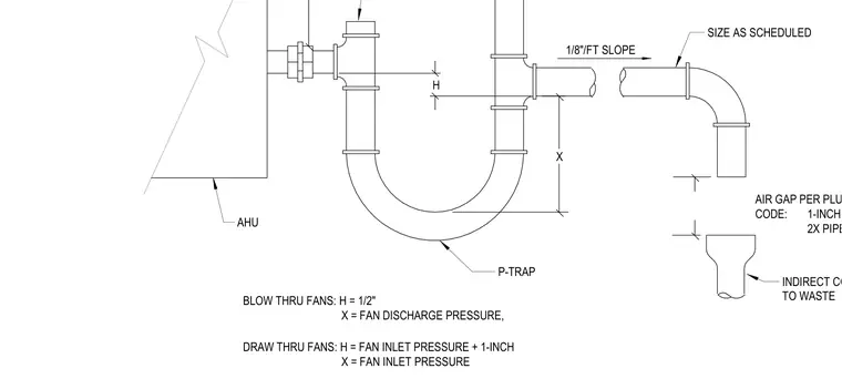
The condensate drain line connects to the air handling unit and routes through a P-trap sized with specific vertical drop dimensions based on fan static pressure. For blow-through fans, dimension H equals 1/2 inch and dimension X equals fan discharge pressure. For draw-through fans, dimension H equals fan inlet pressure plus 1 inch and dimension X equals fan inlet pressure. The discharge piping slopes at 1/8 inch per foot and terminates with an air gap of 1 inch minimum or two times the pipe diameter above the indirect waste connection per plumbing code.
SIZE AS SCHEDULED INDIRECT CONN. TO WASTE 1/8"/FT SLOPE P-TRAP H X AHU BLOW THRU FANS: H = 1/2" X = FAN DISCHARGE PRESSURE, DRAW THRU FANS: H = FAN INLET PRESSURE + 1-INCH X = FAN INLET PRESSURE AIR GAP PER PLUMBING CODE: 1-INCH MIN OR 2X PIPE DIAMETER
Members view this detail in full resolution, download the CAD files (SVG, PDF), and can adapt it in the built-in CAD editor — export DXF, DWG, or PDF.
Start membership